Maintenance and Modifications, Cont’d
Installing a Firmware Upgrade
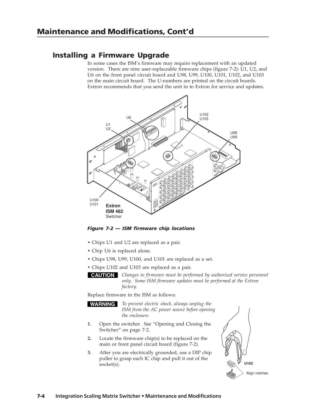
In some cases the ISM’s firmware may require replacement with an updated version. There are nine
U6
U1
U2
U100
U101 Extron
ISM 482
Switcher
U102
U103
U98
U99
B 8![]()
H/HV
|
|
| 7 |
|
|
|
| R |
|
| 6 |
| H/HV | V |
|
|
| R |
|
INPUTS | 5 | R | V |
|
| G |
| ||
4 | R |
|
|
|
|
| G |
| |
3 |
|
|
|
|
R |
| G |
|
|
| 2 |
|
|
| B |
| R |
| G |
|
|
1 |
|
|
| B | |
R |
|
|
| ||
| G |
|
|
| |
|
|
| B |
| |
R | G |
|
|
| H/HV |
|
| B |
|
| |
|
|
|
| H/HV | |
| G | B |
|
|
|
|
|
| H/HV |
| |
G | B |
|
|
|
|
|
| H/HV |
|
| |
| B | H/HV |
|
|
|
|
|
|
| 8 |
|
B | H/HV |
|
|
|
|
|
| 7 |
|
| |
| H/HV |
| 6 |
|
|
|
| 5 |
|
|
|
H/HV |
|
|
|
|
|
4
3
2
1
Figure 7-2 — ISM firmware chip locations
•Chips U1 and U2 are replaced as a pair.
•Chip U6 is replaced alone.
•Chips U98, U99, U100, and U101 are replaced as a set.
•Chips U102 and U103 are replaced as a pair.
CAUTION
Changes to firmware must be performed by authorized service personnel only. Some ISM firmware updates must be performed at the Extron factory.
Replace firmware in the ISM as follows:
To prevent electric shock, always unplug the ISM from the AC power source before opening the enclosure.
1. Open the switcher. See “Opening and Closing the Switcher” on page
2. Locate the firmware chip(s) to be replaced on the main or front panel circuit board (figure
3. | After you are electrically grounded, use a DIP chip |
|
| puller to grasp each IC chip and pull it out of the | U102 |
| socket(s). |
Align notches.