4. Align the slots of each new firmware chip with the angled corners of the socket in the same orientation as the old chip. Gently, but firmly, press the chip into place in the socket.
5. Close the switcher. See “Opening and Closing the Switcher”, starting with step 9 on page
Installing a DVI Output Card
You can install an optional digital visual interface (DVI) output card in the ISS. With the card installed, a additional DVI video output 1 on a standard DVI connector. The DVI output is the video tied to output 1 and is in addition to the standard output 1 RGB video on BNC connector and
Install an optional DVI output card in the ISM as follows:
Changes to electronic components must be performed by authorized service personnel only.
To prevent electric shock, always unplug the ISM from the AC power source before opening the enclosure.
1. Open the switcher. See “Opening and Closing the Switcher” on page
CAUTION
Do not touch any switches or other electronic components inside the ISM. Doing so could damage the ISM. Electrostatic discharge (ESD) can damage IC chips even though you cannot feel it. You must be electrically grounded before proceeding with any electronic component replacement. A grounding wrist strap is recommended.
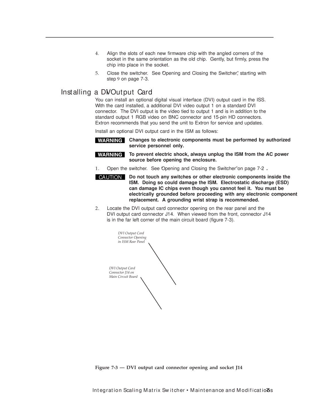
2. Locate the DVI output card connector opening on the rear panel and the DVI output card connector J14. When viewed from the front, connector J14 is in the far left corner of the main circuit board (figure
DVI Output Card
Connector Opening
in ISM Rear Panel
DVI Output Card
Connector J14 on
Main Circuit Board
Figure 7-3 — DVI output card connector opening and socket J14
Integration Scaling Matrix Switcher • Maintenance and Modifications |