Operationeration, cont’d
Front Panel Controls and Indicators
All of the switcher’s controls and indicators are on the front panel (figure
3 | 6 | 7 |
|
|
|
| INPUTS |
|
|
|
|
|
|
|
|
| |
|
|
|
|
|
|
|
|
|
| 1 |
|
|
|
|
BLACK | 1 | 2 | 3 | 4 | 5 | 6 | 7 | 8 | VIDEO |
|
|
|
|
|
|
|
|
|
|
|
|
|
|
| OUTPUTS |
|
|
|
|
MUTE | 1 | 2 | 3 | 4 | 5 | 6 | 7 | 8 | AUDIO |
|
|
|
| ADJUST |
|
|
|
|
|
|
|
|
|
|
|
|
|
| |
|
|
|
|
|
|
|
|
|
| 2 |
|
|
|
|
|
|
|
|
|
|
|
|
|
| COLOR/ | BRT/ | SIZE | CENTER | FILTER |
|
|
|
|
|
|
|
|
|
| TINT | CONT |
|
|
|
|
|
|
|
|
|
|
|
|
|
|
|
| MENU | NEXT |
|
|
|
|
|
|
|
|
|
|
|
|
|
| ISM 482 |
|
|
|
|
|
|
|
|
|
|
|
|
|
| INTEGRATION SEAMLESS SWITCHER |
5 |
|
|
|
| 4 |
|
|
| 1 | 2 |
|
| 8 | 9 |
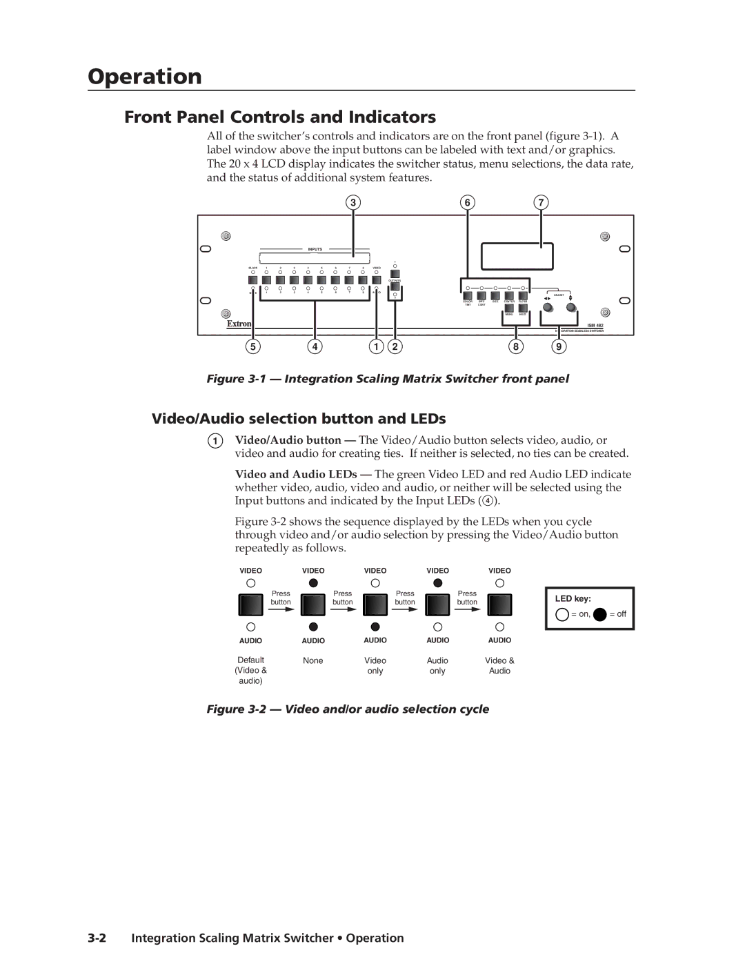
Figure 3-1 — Integration Scaling Matrix Switcher front panel
Video/Audio selection button and LEDs
1Video/Audio button — The Video/Audio button selects video, audio, or video and audio for creating ties. If neither is selected, no ties can be created.
Video and Audio LEDs — The green Video LED and red Audio LED indicate whether video, audio, video and audio, or neither will be selected using the Input buttons and indicated by the Input LEDs ( 4 ).
Figure 3-2 shows the sequence displayed by the LEDs when you cycle through video and/or audio selection by pressing the Video/Audio button repeatedly as follows.
VIDEO | VIDEO | VIDEO | VIDEO | VIDEO |
Press | Press | Press |
| Press |
button | button | button |
| button |
AUDIO | AUDIO | AUDIO | AUDIO | AUDIO |
Default | None | Video | Audio | Video & |
(Video & |
| only | only | Audio |
audio) |
|
|
|
|
LED key:
![]() = on,
= on, ![]() = off
= off