ISM
Precautions
FCC Class B Notice
Integration Scaling Matrix Switcher Quick Start QS-1
Quick Start Integration Scaling Matrix Switcher
QS-2 Integration Scaling Matrix Switcher Quick Start
Quick Start Integration Scaling Matrix Switcher, cont’d
Table of Contents
Table of Contents, cont’d
Integration Scaling Matrix Switcher Table of Contents Iii
Iv Integration Scaling Matrix Switcher Table of Contents
One
About this Manual
About the Switcher
Integration Scaling Matrix Switcher Introduction
Introductiontroduction, cont’d
Extron ISM
Introduction, cont’d
Integration Scaling Matrix Switcher Introduction
Introduction, cont’d
Two
Rack mounting
Installationstallation, cont’d
Mounting the Switcher
Tabletop placement
Mounting instructions
Mounting the switcher
Cabling and Rear Panel Views
Installation, cont’d
Input connections
Captive screw connector wiring for inputs
BNC output connections for Rgbhv and Rgbs video
Standard output connections
Optional output connection
Wiring the network cable
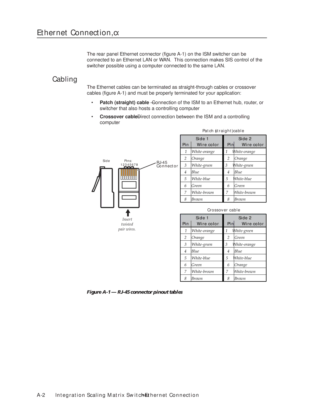
Cabling and RJ-45 connector wiring
Choosing a network cable
RS-232 connection
Configuration
Installation, cont’d
Three
Video/Audio selection button and LEDs
Front Panel Controls and Indicators
Integration Scaling Matrix Switcher Operation
Operationeration, cont’d
Input buttons, LEDs, and label window
Output buttons and LEDs
Front panel input label window
Operation, cont’d
Picture adjustment buttons
Black/Mute button and LEDs
LCD display
Adjustment knobs
Menu control buttons
Front Panel Operations
Power
Extron Electronics ISM 60-425-01 Version
Menu system overview
Input Configuration submenu
Video & Audio Configuration menu
Output Resolution submenu
Output Configuration menu
Operation, cont’d
10 Advanced Configuration menu flowchart
Blanking submenu
Blue-Only Mode and Edge Smoothing submenu
RGB Delay submenu
Test Pattern submenu
Reset submenu
Enhanced Mode submenu
Pixel Phase submenu
PAL Film Mode submenu
Save Preset submenu
User Presets menu
Exit menu
Erase Preset submenu
13 Picture adjustments flowchart
Picture adjustments
Adjust knobs have no mechanical limits to their rotation
Front panel security lockout Executive mode
IP information
Optimizing the Video
Centering controls to position the image
Setting up a DVD source
Optimizing the Audio
Troubleshooting
General checks
Problem Cause
Specific problems
Operation, cont’d
Four
RS-232 Link
Integration Scaling Matrix Switcher Programmer’s Guide
Ethernet Link
Default address
Symbols
Ethernet connection
Ties creation
Switcher-Initiated Messages
Power-up
Programmer’s Guide, cont’d
X2 Col
Test pattern
RGB delay
PAL film mode
Automated adjustments
Switcher error responses
Host-to-Switcher Instructions
Using the command/response table
Programmer’s Guide, cont’d
Command Ascii Command Response Additional description
Command/response table for SIS commands cont’d
Horizontal detail filter RGB and component video inputs
User presets
Verbose mode
Resets
Command/response table for IP SIS commands
Command/response table for IP SIS commands
Command/response table for special function SIS commands
X2 Reconfig message may not be
Command Hex Command Response
Command/response table for advanced instruction set commands
Five
Integration Scaling Matrix Switcher Switcher Software
Installing the software
Control Software for Windows
Software operation via Ethernet
Ethernet protocol settings
Using the control program
Switcher Software, cont’d
Windows Control program window
Button-Label Generator
Using the help program
To run the Button-Label Generator program, click Start
Using the software
Switcher Software, cont’d
Six
EthernetOperation,cont’d
Integration Scaling Matrix Switcher Ethernet Operation
Loading the Startup Control
Control
Creating a tie
Changing the RGB delay
Ethernet Operation, cont’d
Control
Outputting a test pattern
Using Blue-Only mode
Executive mode
Freezing the output
System Configuration
System Configuration
ISM Name field
Administration fields
ISM IP Settings fields
ISM IP Address field
File Management
File Management
I/O Configuration
Input configuration
Ethernet Operation, cont’d
Output rate
Output resolution
Output polarity
Output format
Seven
Opening and Closing the Switcher
Maintenance and Modifications
Grounding wrist strap is recommended
Installing a Firmware Upgrade
Maintenance and Modifications, Cont’d
DVI output card connector opening and socket J14
Installing a DVI Output Card
Output DVI board installation
AAppendix a
Ethernet Connection
Integration Scaling Matrix Switcher Ethernet Connection
Cabling
Pinging to determine the switcher’s IP address
Determining Default Addresses
Pinging to determine the Web IP address
Open
Connecting as a Telnet Client
Ethernet Connection, cont’d
Telnet tips
Close
Escape character and Esc key
Local echo
Set carriage return-line feed
Ethernet Connection, cont’d
AppendixBB
Reference Information
Audio
Reference Information, cont’d
Button Labels
Reference Information, cont’d
Integration Scaling Matrix Switcher Reference Information
Reference Information, cont’d
Extron’s Warranty
Extron Electronics, Europe Beeldschermweg 6C