Quick Start — Integration Scaling Matrix Switcher, cont’d
Step 9
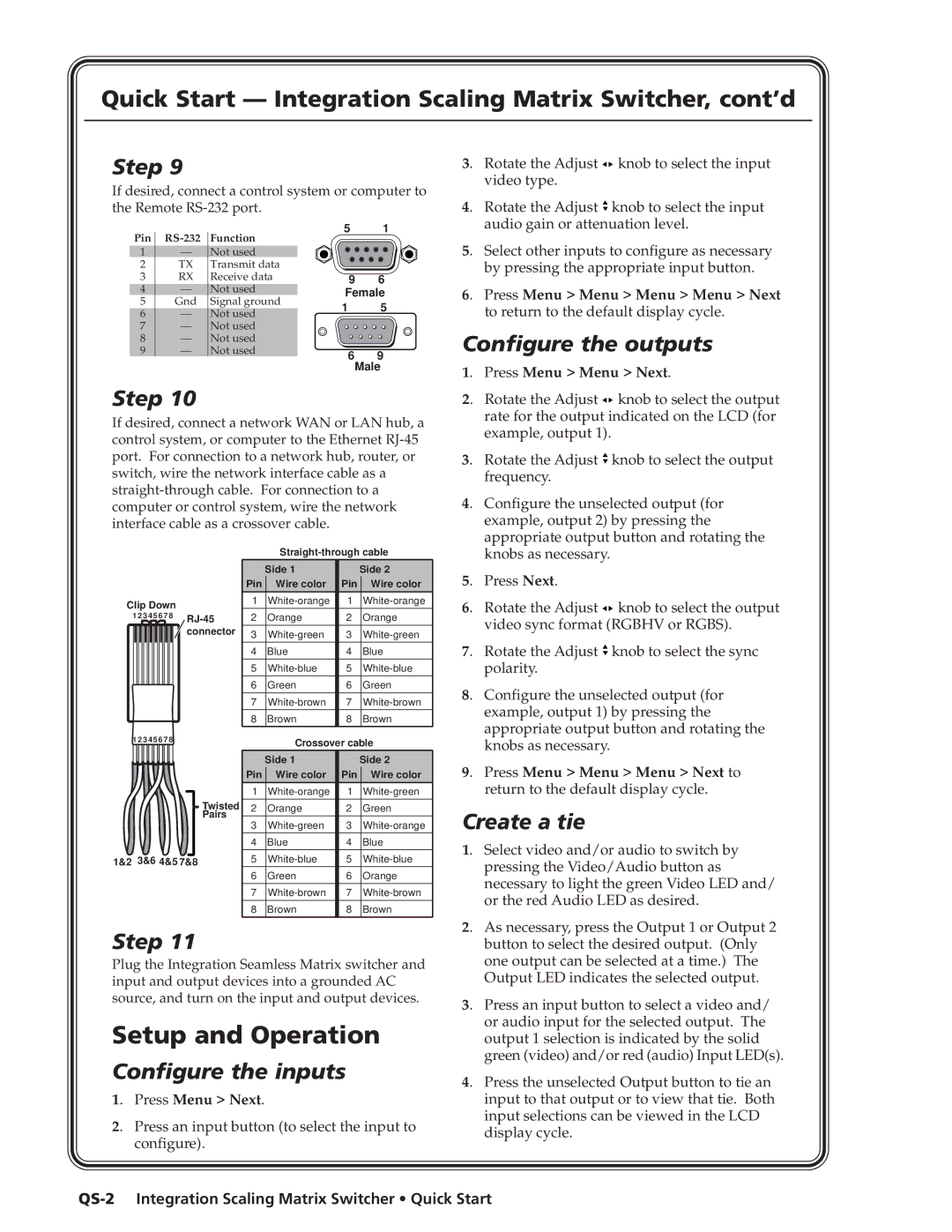
If desired, connect a control system or computer to the Remote
Pin | Function | 5 | 1 | ||
|
| ||||
1 | — | Not used |
|
| |
2 | TX | Transmit data |
|
| |
3 | RX | Receive data | 9 | 6 | |
4 | — | Not used | Female | ||
5 | Gnd | Signal ground | 1 | 5 | |
6 | — | Not used | |||
|
| ||||
7 | — | Not used |
|
| |
8 | — | Not used |
|
| |
9 | — | Not used | 6 | 9 | |
|
|
| |||
Male
Step 10
If desired, connect a network WAN or LAN hub, a control system, or computer to the Ethernet
3. Rotate the Adjust ![]() knob to select the input video type.
knob to select the input video type.
4. Rotate the Adjust ![]() knob to select the input audio gain or attenuation level.
knob to select the input audio gain or attenuation level.
5. Select other inputs to configure as necessary by pressing the appropriate input button.
6. Press Menu > Menu > Menu > Menu > Next to return to the default display cycle.
Configure the outputs
1. | Press Menu > Menu > Next. | |
2. | Rotate the Adjust | knob to select the output |
| rate for the output indicated on the LCD (for | |
| example, output 1). |
|
3. | Rotate the Adjust | knob to select the output |
| frequency. |
|
4. Configure the unselected output (for | ||
| example, output 2) by pressing the | |
| appropriate output button and rotating the | |
Clip Down
1 2 3 4 5 6 7 8
connector
| Side 1 |
| Side 2 |
Pin | Wire color | Pin | Wire color |
1 | 1 | ||
2 | Orange | 2 | Orange |
|
|
|
|
3 | 3 | ||
4 | Blue | 4 | Blue |
|
|
|
|
5 | 5 | ||
6 | Green | 6 | Green |
|
|
|
|
7 | 7 | ||
8 | Brown | 8 | Brown |
| knobs as necessary. |
|
5. | Press Next. |
|
6. | Rotate the Adjust | knob to select the output |
| video sync format (RGBHV or RGBS). | |
7. | Rotate the Adjust | knob to select the sync |
| polarity. |
|
8. Configure the unselected output (for example, output 1) by pressing the appropriate output button and rotating the
1 2 3 4 5 6 7 8 | Crossover cable |
|
knobs as necessary.
Twisted
Pairs
1&2 3&6 4&5 7&8
| Side 1 |
| Side 2 |
Pin | Wire color | Pin | Wire color |
1 | 1 | ||
|
|
|
|
2 | Orange | 2 | Green |
3 | 3 | ||
|
|
|
|
4 | Blue | 4 | Blue |
5 | 5 | ||
|
|
|
|
6 | Green | 6 | Orange |
7 | 7 | ||
8 | Brown | 8 | Brown |
9. Press Menu > Menu > Menu > Next to return to the default display cycle.
Create a tie
1. Select video and/or audio to switch by pressing the Video/Audio button as necessary to light the green Video LED and/ or the red Audio LED as desired.
Step 11
Plug the Integration Seamless Matrix switcher and input and output devices into a grounded AC source, and turn on the input and output devices.
Setup and Operation
Configure the inputs
1. Press Menu > Next.
2. Press an input button (to select the input to configure).
2. As necessary, press the Output 1 or Output 2 button to select the desired output. (Only one output can be selected at a time.) The Output LED indicates the selected output.
3. Press an input button to select a video and/ or audio input for the selected output. The output 1 selection is indicated by the solid green (video) and/or red (audio) Input LED(s).
4. Press the unselected Output button to tie an input to that output or to view that tie. Both input selections can be viewed in the LCD display cycle.