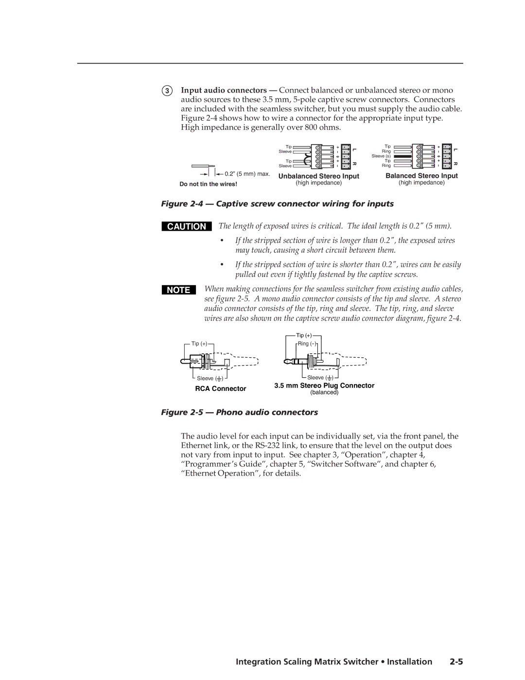
3Input audio connectors — Connect balanced or unbalanced stereo or mono audio sources to these 3.5 mm,
| Tip | L |
| Sleeve | |
|
| |
| Tip | R |
| Sleeve | |
|
| |
0.2” (5 mm) max. | Unbalanced Stereo Input | |
| ||
Do not tin the wires! |
| (high impedance) |
Tip | L | |
Ring | ||
| ||
Sleeve (s) |
| |
Tip | R | |
Ring | ||
|
Balanced Stereo Input
(high impedance)
Figure 2-4 — Captive screw connector wiring for inputs
CAUTION
The length of exposed wires is critical. The ideal length is 0.2" (5 mm).
•If the stripped section of wire is longer than 0.2", the exposed wires may touch, causing a short circuit between them.
•If the stripped section of wire is shorter than 0.2", wires can be easily pulled out even if tightly fastened by the captive screws.
When making connections for the seamless switcher from existing audio cables, see figure
Tip (+)
![]() Sleeve (
Sleeve (![]() )
)
Tip (+)
Ring
Sleeve (![]() )
)
RCA Connector | 3.5 mm Stereo Plug Connector | |
(balanced) | ||
|
Figure 2-5 — Phono audio connectors
The audio level for each input can be individually set, via the front panel, the Ethernet link, or the
Integration Scaling Matrix Switcher • Installation |