Chapter 5. Using BCAdmin™
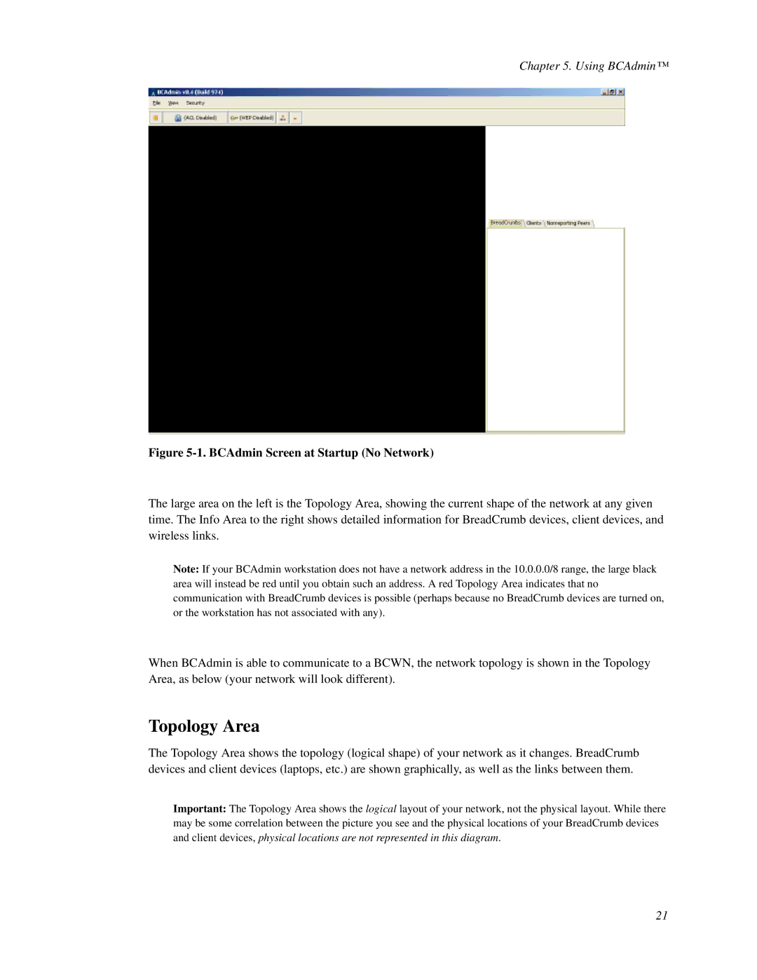
Figure 5-1. BCAdmin Screen at Startup (No Network)
The large area on the left is the Topology Area, showing the current shape of the network at any given time. The Info Area to the right shows detailed information for BreadCrumb devices, client devices, and wireless links.
Note: If your BCAdmin workstation does not have a network address in the 10.0.0.0/8 range, the large black area will instead be red until you obtain such an address. A red Topology Area indicates that no communication with BreadCrumb devices is possible (perhaps because no BreadCrumb devices are turned on, or the workstation has not associated with any).
When BCAdmin is able to communicate to a BCWN, the network topology is shown in the Topology Area, as below (your network will look different).
Topology Area
The Topology Area shows the topology (logical shape) of your network as it changes. BreadCrumb devices and client devices (laptops, etc.) are shown graphically, as well as the links between them.
Important: The Topology Area shows the logical layout of your network, not the physical layout. While there may be some correlation between the picture you see and the physical locations of your BreadCrumb devices and client devices, physical locations are not represented in this diagram.
21