DECATHLON SERIES GAS FRYERS
CHAPTER 1: SERVICE PROCEDURES
Interface Boards (cont.)
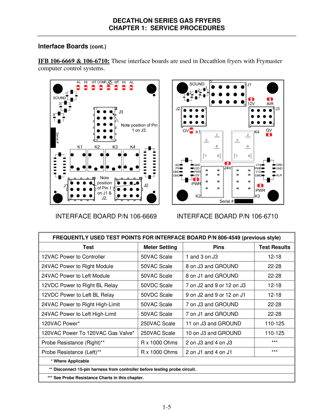
IFB
INTERFACE BOARD P/N | INTERFACE BOARD P/N |
FREQUENTLY USED TEST POINTS FOR INTERFACE BOARD P/N
Test | Meter Setting | Pins | Test Results |
|
|
|
|
12VAC Power to Controller | 50VAC Scale | 1 and 3 on J3 | |
|
|
|
|
24VAC Power to Right Module | 50VAC Scale | 8 on J3 and GROUND | |
|
|
|
|
24VAC Power to Left Module | 50VAC Scale | 8 on J1 and GROUND | |
|
|
|
|
12VDC Power to Right BL Relay | 50VDC Scale | 7 on J2 and 9 or 12 on J3 | |
|
|
|
|
12VDC Power to Left BL Relay | 50VDC Scale | 9 on J2 and 9 or 12 on J1 | |
|
|
|
|
24VAC Power to Right | 50VAC Scale | 7 on J3 and GROUND | |
|
|
|
|
24VAC Power to Left | 50VAC Scale | 7 on J1 and GROUND | |
|
|
|
|
120VAC Power* | 250VAC Scale | 11 on J3 and GROUND | |
|
|
|
|
120VAC Power To 120VAC Gas Valve* | 250VAC Scale | 10 on J3 and GROUND | |
|
|
|
|
Probe Resistance (Right)** | R x 1000 Ohms | 2 on J3 and 4 on J3 | *** |
|
|
|
|
Probe Resistance (Left)** | R x 1000 Ohms | 2 on J1 and 4 on J1 | *** |
|
|
|
|
*Where Applicable
**Disconnect
***See Probe Resistance Charts in this chapter.
