Manuals
/
Fujitsu
/
Computer Equipment
/
Printer
Fujitsu
C145-C037-01EN
manual
Ventura Math ID6M
Models:
C145-C037-01EN
1
113
123
123
Download
123 pages
16.02 Kb
110
111
112
113
114
115
116
117
Specifications
Block Diagram
Parallel interface signals
Error display
Appendix a Symbol Sets
Control panel Indicators
Maintenance
Model Configuration
Command Sets
Periodic Replacement Parts
Page 113
Image 113
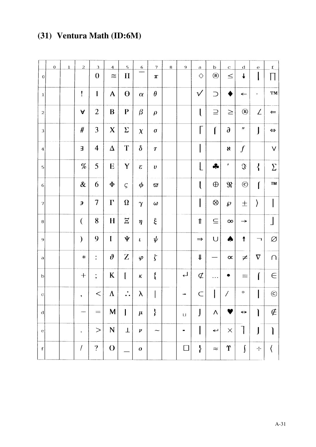
(31) Ventura Math (ID:6M)
A-31
Page 112
Page 114
Page 113
Image 113
Page 112
Page 114
Contents
Printer Product Description
Fujitsu Limited
Printer Product Description
Page
Revision Record
Fujitsu Canada INC
Fujitsu Computer Products of AMERICA, INC
Fujitsu ESPAÑA, S.A
Fujitsu France S.A
Preface
Contents
Options and Supplies
HP LaserJet 5 Emulation PostScript Level 2 Emulation
Illustrations and Tables
Features
PrintPartner 20W printer
Easy Paper Handling
Fine Print Quality
Quiet Operation
Compact, Lightweight, and Small Footprint Design
High Reliability and Easy Maintenance
Environment Friendly
Wide Variety of Interfaces and Emulations
Duplex Printing Capability
User-Friendly Operation
Wide Variety of Media
Extendability
PrintPartner 20W page printer
Model Configuration
Printer block diagram
Block Diagram
Page
Structure with duplex unit + paper trays 1 to
Structure
General Specifications
Specifications
Double-sided printing
Single-sided printing
Page
Conditions and environment
Conditions and environment
Mttr
Mtbf
Conditions
PCL
PCL6
CPU
ROM
Page
Specification
MFF
Paper Specifications
Type, size, and thickness
Printing area
Printing area
Paper storage
Other precautions
Page
Control Panel
Control panel Indicators
2 LCD
Menu mode
Buttons
Simply press the button
Robust XON
Printer utility programs MarkVision
Printer Utility Programs
MenuBarFunctions
Main Menu and Menu Bar Functions
Ppmenu
Send Exit
Printer Drivers
Standard printer drivers for Windows 95/98 and NT
Standard printer drivers for Windows NT
FPS printer drivers for Windows 95/98
Yes* or No
FPS printer drivers for Windows NT
Page
Hardware requirements
Parallel Interface Ieee 1284-B Connector
Overview
Direction Description Number
Parallel interface signals
Return Signal Pin Line pin
Connector Return Signal Pin Line pin
Not used
Data transmission timing
4a Data transmission timing compatible mode
4b Data transmission timing nibble mode
Parallel interface output circuit
Parallel Interface Ieee 1284-C Connector
Parallel interface connector IEEE1284-C
Dstb
PRM
Nibble mode Input Reserved *1
8a Data transmission timing compatible mode
8b Data transmission timing nibble mode
RS-232C interface input circuit
RS-232C Serial Interface
Pin Signal name Direction Description Number
RS-232C interface signals
RTS
DSR
CTS
Serial data format
Computer DTE Printer DTE
Computer DTE Printer DTE
Page
Printer emulation Option to be selected in menu mode
Command Sets
Printer emulation
FPS
Control code Description
HP LaserJet 5 command set summary HP LaserJet 5 PCL mode
Level 1 escape code Description
Level 2 escape code Description
LF/FF
Level 3 escape code
Page
Page
Page
Page
Configuration and Status Set Commands
HP LaserJet 5 HP-GL/2 mode
Picture Frame Set Commands
Line and Fill Attributes Select Commands
Vector Commands
Polygon Commands
Char Function
Character Plotting Commands
ETX
DEL
Kernel Commands Description
HP LaserJet 5 PJL mode
Job Separation Commands Description
Environment Commands Description
Additional Commands Description
Status Readback Commands Description
PostScript Operators Commands
Maintenance Philosophy
Preventive Maintenance
Diagnostics
Error display
Self test printing
Maintenance Tool
Recommended Spare Parts
Options
Options and Supplies
Documentation
Periodic Replacement Parts
Consumables
Appendix a Symbol Sets
ISO8859-1 Latin 1 ID0N
PC-8 ID10U
PC-8 Danish/Norwegian, ID11U
PC-85 ID12U
Windows 3.1 Latin 1 ID19U
DeskTop ID7J
PS Text ID10J
Ventura International ID13J
Ventura US ID14J
Microsoft Publishing ID6J
Legal ID1U
ISO United Kingdom ID1E
Ascii ID0U
ISO Swedish ID0S
ISO Italian ID0I
ISO Spanish ID2S
ISO German ID1G
ISO Norwegian ID0D
ISO French ID1F
Windows 3.0 Latin 1 ID9U
MC Text ID12J
23 PC-852 ID17U
PC-Turkish ID9T
Windows 3.1 Latin 2 ID9E
Windows 3.1 Latin 5 ID5T
ISO 8859-1 Latin 2 ID2N
ISO 8859-2 Latin 2 ID5N
Math-8 ID8M
PS Math ID5M
Ventura Math ID6M
PI Font ID15U
Symbol ID19M
Wingdings ID579L
Scalable fonts
HP LaserJet 5 Emulation
One bitmap font
Page
Page
PostScript Level 2 Emulation
Position Label
Contents
Top
Page
Image
Contents