5.3.2Connector pin assignment
Connector (cable side): Shielded plug
MOLEX
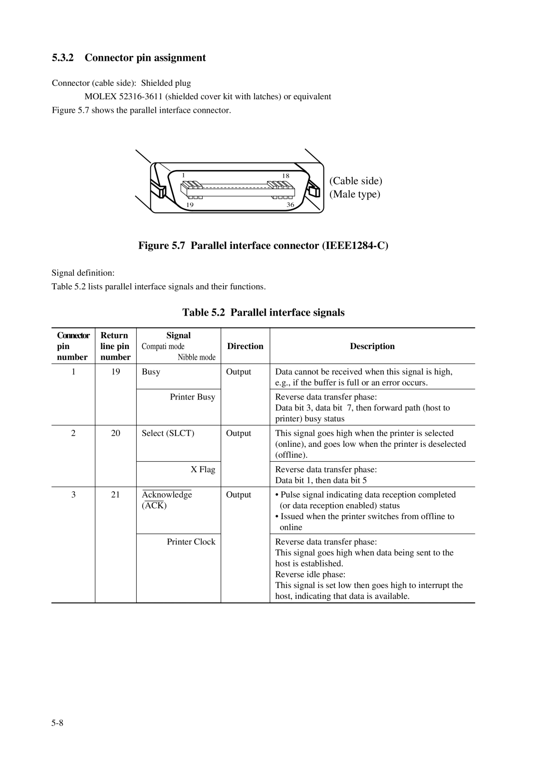
1 | 18 |
19 | 36 |
(Cable side) (Male type)
Figure 5.7 Parallel interface connector (IEEE1284-C)
Signal definition:
Table 5.2 lists parallel interface signals and their functions.
|
|
|
|
| Table 5.2 | Parallel interface signals | |||
|
|
|
|
|
|
|
|
|
|
Connector | Return |
|
|
| Signal |
|
|
| |
pin | line pin | Compati mode |
| Direction | Description | ||||
number | number |
|
|
| Nibble mode |
|
|
| |
|
|
|
|
|
|
|
|
|
|
1 | 19 | Busy |
| Output | Data cannot be received when this signal is high, | ||||
|
|
|
|
|
|
|
|
| e.g., if the buffer is full or an error occurs. |
|
|
|
|
|
|
|
|
|
|
|
|
|
|
| Printer Busy |
|
| Reverse data transfer phase: | |
|
|
|
|
|
|
|
|
| Data bit 3, data bit 7, then forward path (host to |
|
|
|
|
|
|
|
|
| printer) busy status |
|
|
|
|
|
|
|
|
|
|
2 | 20 | Select (SLCT) |
| Output | This signal goes high when the printer is selected | ||||
|
|
|
|
|
|
|
|
| (online), and goes low when the printer is deselected |
|
|
|
|
|
|
|
|
| (offline). |
|
|
|
|
|
|
|
|
|
|
|
|
|
|
| X Flag |
|
| Reverse data transfer phase: | |
|
|
|
|
|
|
|
|
| Data bit 1, then data bit 5 |
|
|
|
|
|
|
|
|
|
|
3 | 21 |
|
|
|
|
|
| Output | • Pulse signal indicating data reception completed |
Acknowledge |
| ||||||||
|
|
| (ACK) |
|
|
| (or data reception enabled) status | ||
|
|
|
|
|
|
|
|
| • Issued when the printer switches from offline to |
|
|
|
|
|
|
|
|
| online |
|
|
|
|
|
|
|
|
|
|
|
|
|
|
| Printer Clock |
|
| Reverse data transfer phase: | |
|
|
|
|
|
|
|
|
| This signal goes high when data being sent to the |
|
|
|
|
|
|
|
|
| host is established. |
|
|
|
|
|
|
|
|
| Reverse idle phase: |
|
|
|
|
|
|
|
|
| This signal is set low then goes high to interrupt the |
|
|
|
|
|
|
|
|
| host, indicating that data is available. |
|
|
|
|
|
|
|
|
|
|