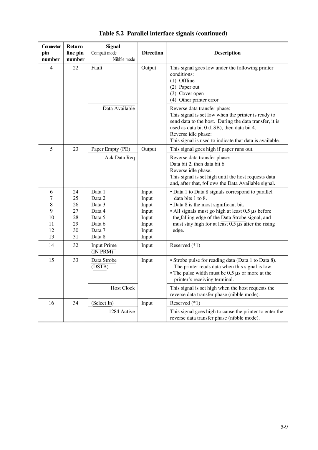
Table 5.2 Parallel interface signals (continued)
| Connector | Return |
|
|
|
|
| Signal |
|
|
|
|
| |||
| pin | line pin |
| Compati mode | Direction |
| Description | |||||||||
| number | number |
|
|
|
|
|
| Nibble mode |
|
|
|
|
| ||
|
|
|
|
|
|
|
|
|
|
|
|
|
| |||
| 4 | 22 |
|
|
|
|
|
|
|
| Output | This signal goes low under the following printer | ||||
|
| Fault | ||||||||||||||
|
|
|
|
|
|
|
|
|
|
|
|
| conditions: | |||
|
|
|
|
|
|
|
|
|
|
|
|
| (1) | Offline | ||
|
|
|
|
|
|
|
|
|
|
|
|
| (2) | Paper out | ||
|
|
|
|
|
|
|
|
|
|
|
|
| (3) Cover open | |||
|
|
|
|
|
|
|
|
|
|
|
|
| (4) | Other printer error | ||
|
|
|
|
|
|
|
|
|
|
|
|
|
| |||
|
|
|
|
|
|
|
|
|
|
|
| |||||
|
|
|
|
|
| Data Available |
| Reverse data transfer phase: | ||||||||
|
|
|
|
|
|
|
|
|
|
|
|
| This signal is set low when the printer is ready to | |||
|
|
|
|
|
|
|
|
|
|
|
|
| send data to the host. During the data transfer, it is | |||
|
|
|
|
|
|
|
|
|
|
|
|
| used as data bit 0 (LSB), then data bit 4. | |||
|
|
|
|
|
|
|
|
|
|
|
|
| Reverse idle phase: | |||
|
|
|
|
|
|
|
|
|
|
|
|
| This signal is used to indicate that data is available. | |||
|
|
|
|
|
|
|
|
|
|
|
|
|
| |||
| 5 | 23 |
| Paper Empty (PE) | Output | This signal goes high if paper runs out. | ||||||||||
|
|
|
|
|
|
|
|
|
|
|
|
|
| |||
|
|
|
|
|
|
|
| Ack Data Req |
| Reverse data transfer phase: | ||||||
|
|
|
|
|
|
|
|
|
|
|
|
| Data bit 2, then data bit 6 | |||
|
|
|
|
|
|
|
|
|
|
|
|
| Reverse idle phase: | |||
|
|
|
|
|
|
|
|
|
|
|
|
| This signal is set high until the host requests data | |||
|
|
|
|
|
|
|
|
|
|
|
|
| and, after that, follows the Data Available signal. | |||
|
|
|
|
|
|
|
|
|
|
|
|
|
| |||
| 6 | 24 |
| Data 1 | Input | • Data 1 to Data 8 signals correspond to parallel | ||||||||||
| 7 | 25 |
| Data 2 | Input | data bits 1 to 8. | ||||||||||
| 8 | 26 |
| Data 3 | Input | • Data 8 is the most significant bit. | ||||||||||
| 9 | 27 |
| Data 4 | Input | • All signals must go high at least 0.5 μs before | ||||||||||
| 10 | 28 |
| Data 5 | Input | the falling edge of the Data Strobe signal, and | ||||||||||
| 11 | 29 |
| Data 6 | Input |
|
|
| ||||||||
| must stay high for at least 0.5 μs after the rising | |||||||||||||||
| 12 | 30 |
| Data 7 | Input | edge. | ||||||||||
| 13 | 31 |
| Data 8 | Input |
|
|
|
| |||||||
|
|
|
|
|
|
|
|
|
|
|
|
|
| |||
| 14 | 32 |
| Input Prime | Input | Reserved (*1) | ||||||||||
|
|
|
|
|
|
|
|
|
|
|
| |||||
|
|
|
| (IN PRM) |
|
|
|
|
| |||||||
| 15 | 33 |
| Data Strobe | Input | • Strobe pulse for reading data (Data 1 to Data 8). | ||||||||||
|
|
|
|
|
|
|
|
|
|
|
|
| The printer reads data when this signal is low. | |||
|
|
|
| (DSTB) |
| |||||||||||
|
|
|
|
|
|
|
|
|
|
|
|
| • The pulse width must be 0.5 μs or more at the | |||
|
|
|
|
|
|
|
|
|
|
|
|
| ||||
|
|
|
|
|
|
|
|
|
|
|
|
| printer’s receiving terminal. | |||
|
|
|
|
|
|
|
|
|
|
|
|
|
| |||
|
|
|
|
|
|
|
|
| Host Clock |
| This signal is set high when the host requests the | |||||
|
|
|
|
|
|
|
|
|
|
|
|
| reverse data transfer phase (nibble mode). | |||
|
|
|
|
|
|
|
|
|
|
|
|
|
| |||
| 16 | 34 |
| (Select In) | Input | Reserved (*1) | ||||||||||
|
|
|
|
|
|
|
|
|
|
|
|
|
| |||
|
|
|
|
|
|
|
|
| 1284 Active |
| This signal goes high to cause the printer to enter the | |||||
|
|
|
|
|
|
|
|
|
|
|
|
| reverse data transfer phase (nibble mode). | |||
|
|
|
|
|
|
|
|
|
|
|
|
|
|
|
|
|