5.4.2Connector pin assignment
Connector (cable side):
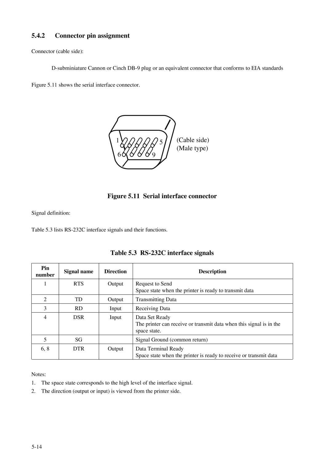
Figure 5.11 shows the serial interface connector.
1 | 5 | (Cable side) |
6 | 9 | (Male type) |
|
Figure 5.11 Serial interface connector
Signal definition:
Table 5.3 lists
Table 5.3 RS-232C interface signals
Pin | Signal name | Direction | Description | |
number | ||||
|
|
| ||
|
|
|
| |
1 | RTS | Output | Request to Send | |
|
|
| Space state when the printer is ready to transmit data | |
|
|
|
| |
2 | TD | Output | Transmitting Data | |
|
|
|
| |
3 | RD | Input | Receiving Data | |
|
|
|
| |
4 | DSR | Input | Data Set Ready | |
|
|
| The printer can receive or transmit data when this signal is in the | |
|
|
| space state. | |
|
|
|
| |
5 | SG |
| Signal Ground (common return) | |
|
|
|
| |
6, 8 | DTR | Output | Data Terminal Ready | |
|
|
| Space state when the printer is ready to receive or transmit data |
Notes:
1.The space state corresponds to the high level of the interface signal.
2.The direction (output or input) is viewed from the printer side.