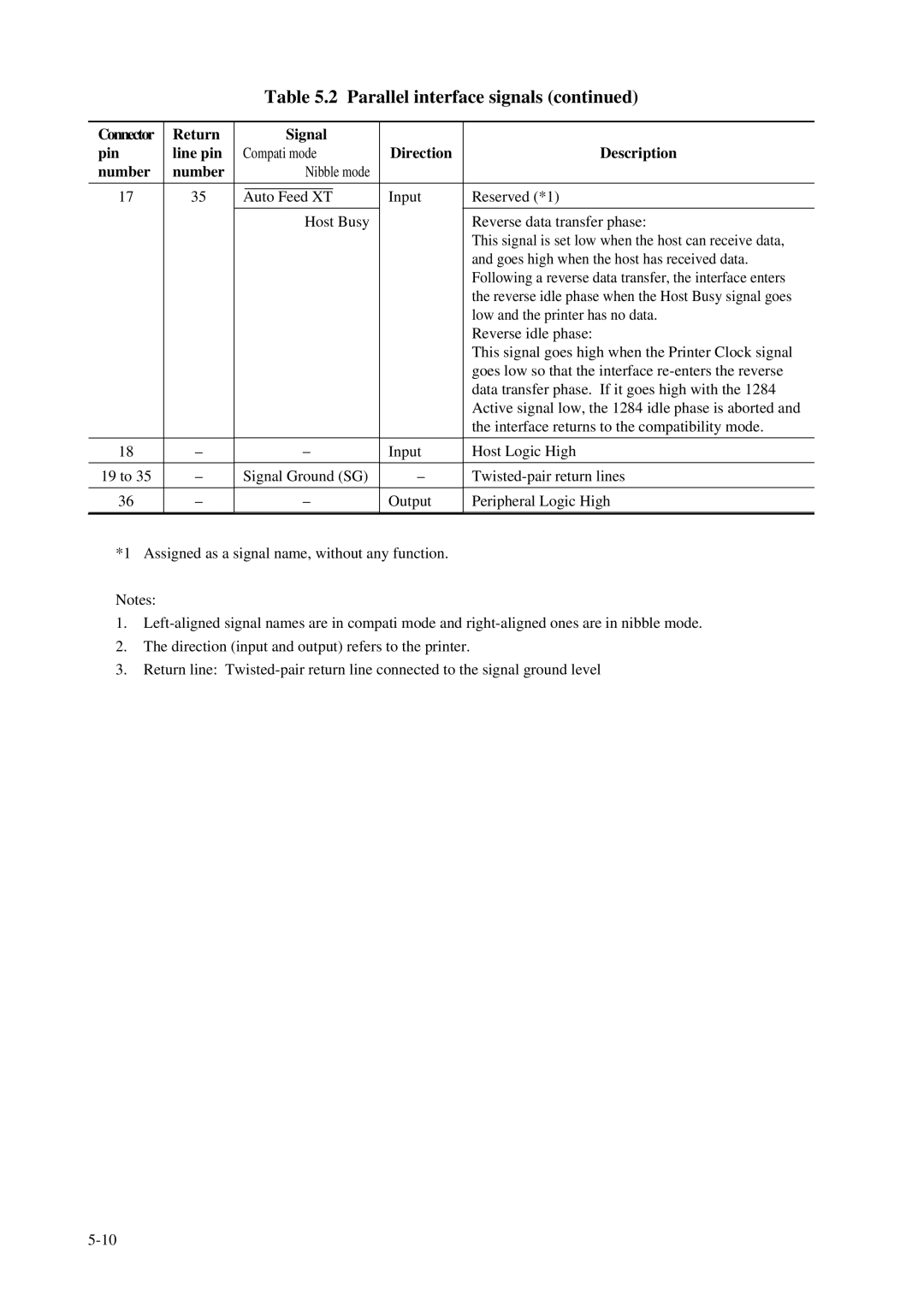
Table 5.2 Parallel interface signals (continued)
Connector | Return |
| Signal |
|
| |
pin | line pin | Compati mode | Direction | Description | ||
number | number |
| Nibble mode |
|
| |
|
|
|
|
|
|
|
17 | 35 |
|
|
| Input | Reserved (*1) |
Auto Feed XT | ||||||
|
|
| Host Busy |
| Reverse data transfer phase: | |
|
|
|
|
|
| This signal is set low when the host can receive data, |
|
|
|
|
|
| and goes high when the host has received data. |
|
|
|
|
|
| Following a reverse data transfer, the interface enters |
|
|
|
|
|
| the reverse idle phase when the Host Busy signal goes |
|
|
|
|
|
| low and the printer has no data. |
|
|
|
|
|
| Reverse idle phase: |
|
|
|
|
|
| This signal goes high when the Printer Clock signal |
|
|
|
|
|
| goes low so that the interface |
|
|
|
|
|
| data transfer phase. If it goes high with the 1284 |
|
|
|
|
|
| Active signal low, the 1284 idle phase is aborted and |
|
|
|
|
|
| the interface returns to the compatibility mode. |
|
|
|
|
|
|
|
18 | – |
| – | Input | Host Logic High | |
|
|
|
|
|
|
|
19 to 35 | – | Signal Ground (SG) | – | |||
|
|
|
|
|
|
|
36 | – |
| – | Output | Peripheral Logic High | |
|
|
|
|
|
|
|
*1 Assigned as a signal name, without any function.
Notes:
1.
2.The direction (input and output) refers to the printer.
3.Return line: