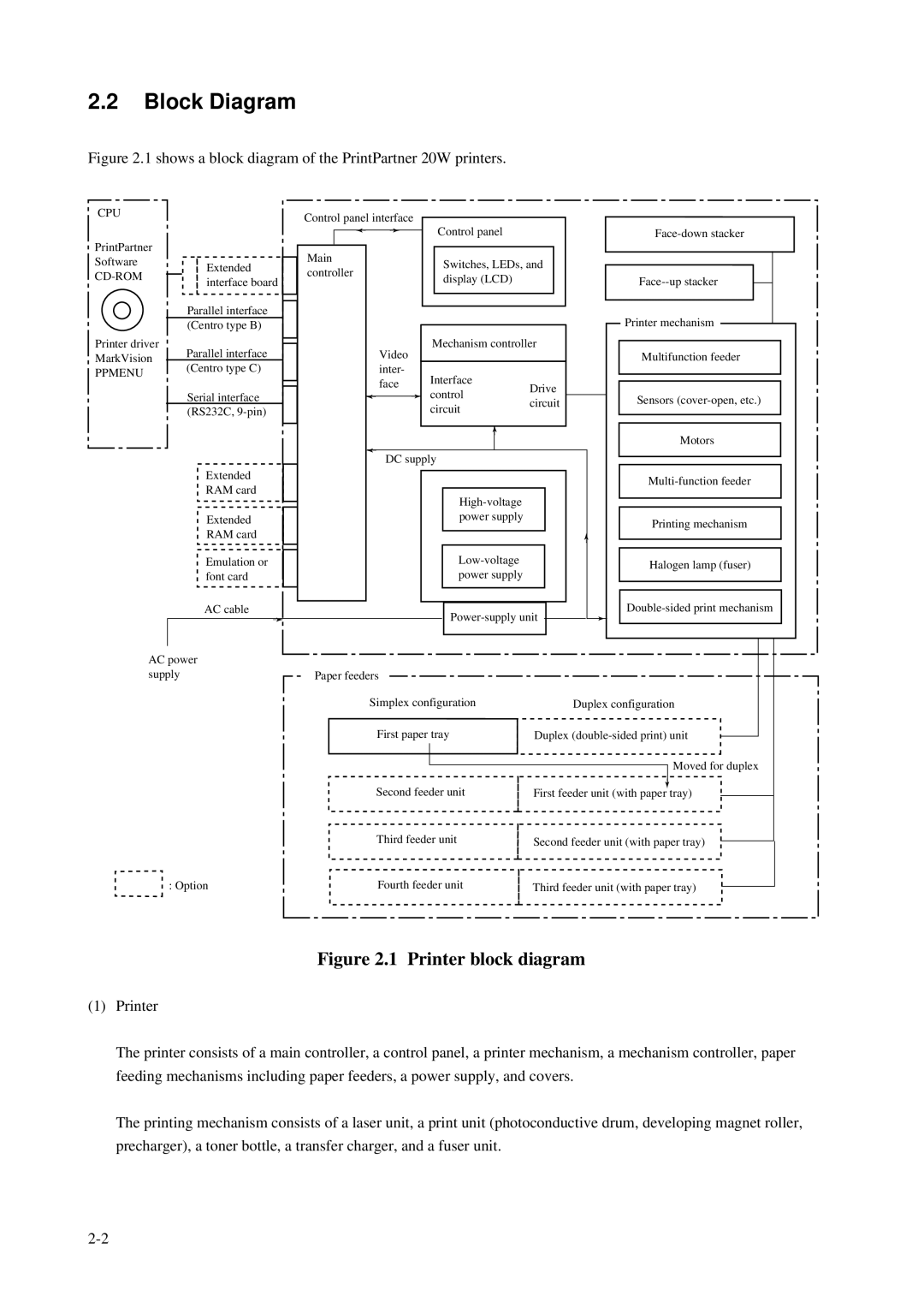
2.2Block Diagram
Figure 2.1 shows a block diagram of the PrintPartner 20W printers.
CPU
PrintPartner
Software
Printer driver MarkVision
PPMENU
Extended interface board
Parallel interface
(Centro type B)
Parallel interface
(Centro type C)
Serial interface
(RS232C,
Extended
RAM card
Extended
RAM card
Emulation or font card
AC cable
➛
Control panel interface |
|
|
|
|
|
| ||||
| Control panel |
|
|
| ||||||
| ➛ | ➛ |
|
|
|
|
| |||
|
|
|
|
|
| |||||
|
|
|
|
|
|
|
|
|
| |
Main |
|
|
|
|
| Switches, LEDs, and |
| |||
controller |
|
|
|
|
|
| ||||
|
|
|
|
| display (LCD) |
|
|
| ||
|
|
|
|
|
|
|
|
|
| |
|
|
|
|
|
|
|
|
|
| |
|
|
|
|
|
|
|
|
|
|
|
|
|
|
|
|
|
|
|
|
|
|
|
|
| Video |
| Mechanism controller | |||||
|
|
|
|
|
|
|
|
|
| |
|
|
| inter- |
| Interface |
|
|
| ||
|
|
| face |
| Drive | |||||
|
|
|
| control | ||||||
|
| ➛ |
| ➛ | ||||||
|
|
| circuit | |||||||
|
|
|
|
| circuit | |||||
|
|
|
|
|
|
|
| |||
|
|
|
|
|
|
|
|
|
|
|
|
|
|
|
|
|
| ➛ |
|
|
|
|
| ➛ | DC supply |
|
|
| ||||
|
|
|
|
|
| |||||
|
|
|
|
|
|
|
|
|
|
|
|
|
|
|
|
|
|
|
|
|
|
|
|
|
|
|
|
|
|
|
| |
|
|
|
|
|
|
| power supply |
|
|
|
|
|
|
|
|
|
|
|
|
|
|
|
|
|
|
|
|
|
|
|
|
|
|
|
|
|
|
|
|
|
|
| |
|
|
|
|
|
|
| power supply |
|
|
|
|
|
|
|
|
|
|
|
|
| |
|
|
|
|
|
|
|
|
|
|
|
|
|
|
|
|
|
|
|
| ||
|
|
|
|
|
|
|
|
|
|
|
➛
➛
Printer mechanism
Multifunction feeder
Sensors
Motors
Printing mechanism
Halogen lamp (fuser)
AC power supply
: Option
|
|
|
|
|
|
|
|
|
|
Paper feeders |
|
|
|
|
|
|
|
|
|
|
|
|
|
|
|
|
|
|
|
Simplex configuration | Duplex configuration |
|
| ||||||
First paper tray | Duplex |
|
|
|
| ||||
|
|
|
| ||||||
|
|
|
|
| Moved for duplex |
| |||
|
|
|
|
|
| ||||
Second feeder unit |
| ➛ |
| ||||||
First feeder unit (with paper tray) |
|
|
| ||||||
|
|
| |||||||
Third feeder unit | Second feeder unit (with paper tray) |
|
|
| |||||
|
|
| |||||||
Fourth feeder unit | Third feeder unit (with paper tray) |
|
| ||||||
|
| ||||||||
Figure 2.1 Printer block diagram
(1)Printer
The printer consists of a main controller, a control panel, a printer mechanism, a mechanism controller, paper feeding mechanisms including paper feeders, a power supply, and covers.
The printing mechanism consists of a laser unit, a print unit (photoconductive drum, developing magnet roller, precharger), a toner bottle, a transfer charger, and a fuser unit.