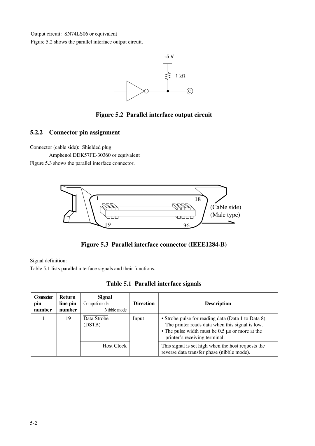
Output circuit: SN74LS06 or equivalent
Figure 5.2 shows the parallel interface output circuit.
+5 V
1 kΩ
Figure 5.2 Parallel interface output circuit
5.2.2Connector pin assignment
Connector (cable side): Shielded plug Amphenol
Figure 5.3 shows the parallel interface connector.
1
19
18
(Cable side) (Male type)
36
Figure 5.3 Parallel interface connector (IEEE1284-B)
Signal definition:
Table 5.1 lists parallel interface signals and their functions.
|
|
|
|
| Table 5.1 | Parallel interface signals | |||
|
|
|
|
|
|
|
| ||
Connector | Return |
|
| Signal |
|
|
| ||
pin | line pin |
| Compati mode |
| Direction | Description | |||
number | number |
|
|
| Nibble mode |
|
|
| |
|
|
|
|
|
|
|
|
|
|
1 | 19 |
|
|
|
|
|
| Input | • Strobe pulse for reading data (Data 1 to Data 8). |
| Data Strobe | ||||||||
|
|
|
| (DSTB) |
|
|
| The printer reads data when this signal is low. | |
|
|
|
|
|
|
|
|
| • The pulse width must be 0.5 μs or more at the |
|
|
|
|
|
|
|
|
| printer’s receiving terminal. |
|
|
|
|
|
|
|
|
|
|
|
|
|
|
| Host Clock |
|
| This signal is set high when the host requests the | |
|
|
|
|
|
|
|
|
| reverse data transfer phase (nibble mode). |
|
|
|
|
|
|
|
|
|
|