Installation Requirements
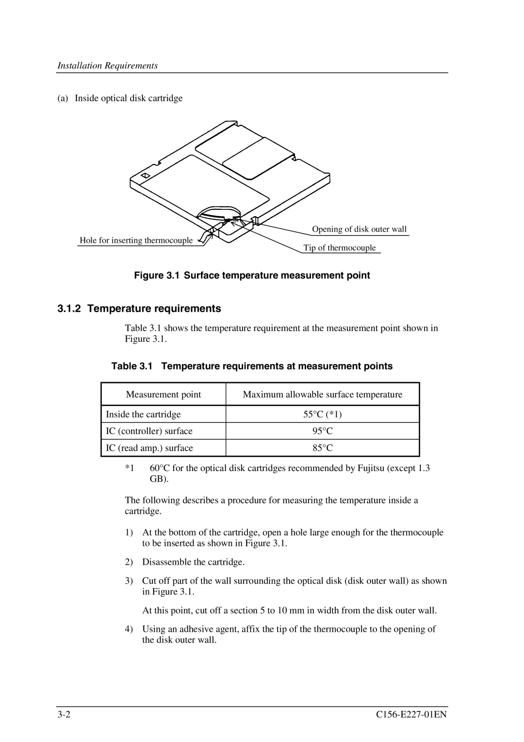
(a) Inside optical disk cartridge
Opening of disk outer wall
Hole for inserting thermocouple
Tip of thermocouple
Figure 3.1 Surface temperature measurement point
3.1.2 Temperature requirements
Table 3.1 shows the temperature requirement at the measurement point shown in Figure 3.1.
Table 3.1 Temperature requirements at measurement points
Measurement point | Maximum allowable surface temperature |
|
|
Inside the cartridge | 55°C (*1) |
|
|
IC (controller) surface | 95°C |
|
|
IC (read amp.) surface | 85°C |
|
|
*1 60°C for the optical disk cartridges recommended by Fujitsu (except 1.3 GB).
The following describes a procedure for measuring the temperature inside a cartridge.
1)At the bottom of the cartridge, open a hole large enough for the thermocouple to be inserted as shown in Figure 3.1.
2)Disassemble the cartridge.
3)Cut off part of the wall surrounding the optical disk (disk outer wall) as shown in Figure 3.1.
At this point, cut off a section 5 to 10 mm in width from the disk outer wall.
4)Using an adhesive agent, affix the tip of the thermocouple to the opening of the disk outer wall.