Installation Requirements
(3) Cable selection mode setting
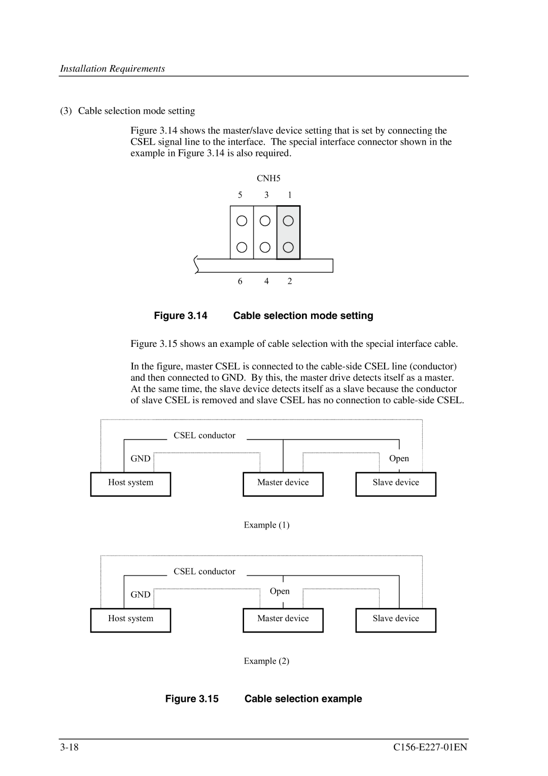
Figure 3.14 shows the master/slave device setting that is set by connecting the CSEL signal line to the interface. The special interface connector shown in the example in Figure 3.14 is also required.
| CNH5 |
|
5 | 3 | 1 |
6 | 4 | 2 |
Figure 3.14 Cable selection mode setting
Figure 3.15 shows an example of cable selection with the special interface cable.
In the figure, master CSEL is connected to the cable-side CSEL line (conductor) and then connected to GND. By this, the master drive detects itself as a master. At the same time, the slave device detects itself as a slave because the conductor of slave CSEL is removed and slave CSEL has no connection to cable-side CSEL.
GND ![]()
Host system
GND ![]()
CSEL conductor
Master device
Example (1)
CSEL conductor
Open
Open
Slave device
Host system
Master device
Slave device
Example (2)