Interface
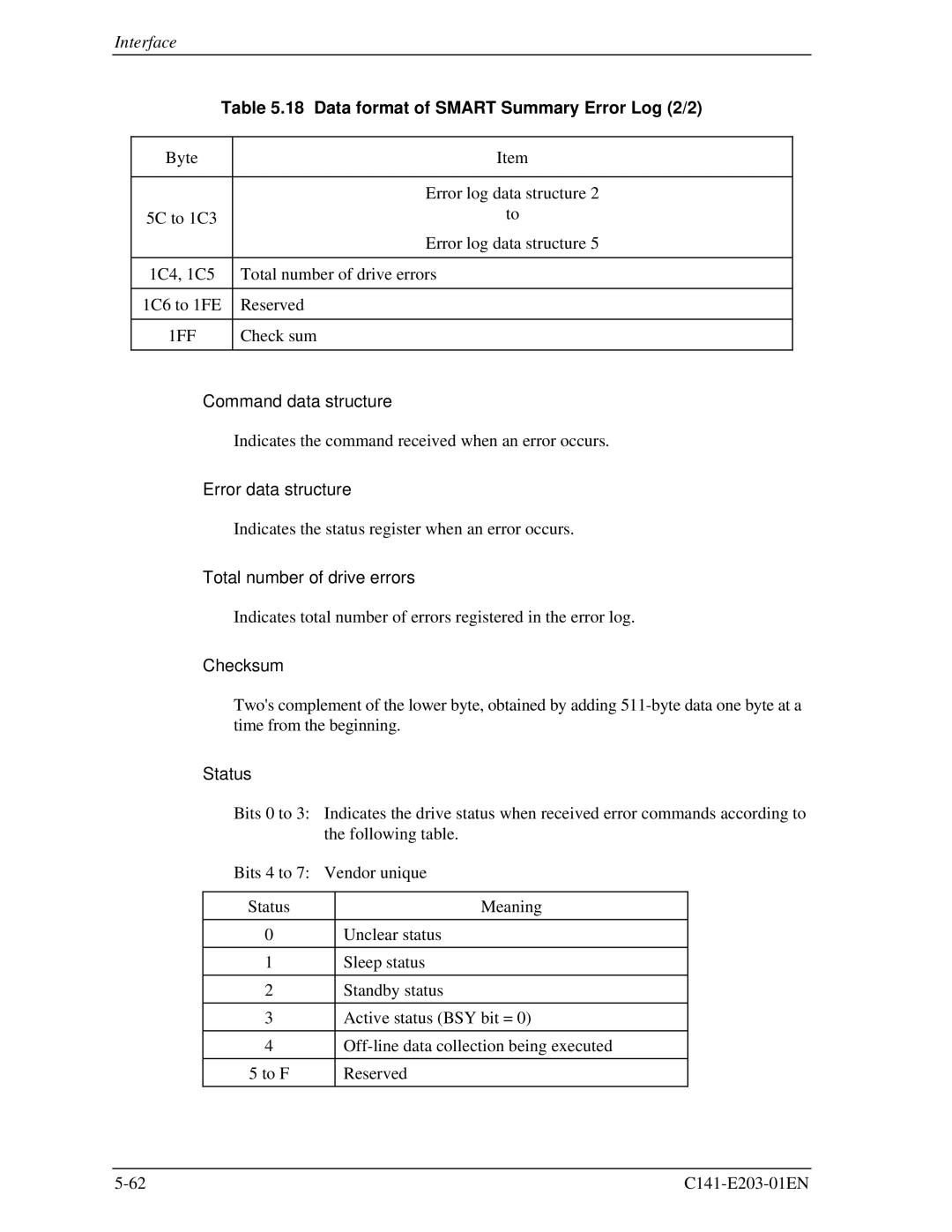
Table 5.18 Data format of SMART Summary Error Log (2/2)
Byte | Item |
|
|
| Error log data structure 2 |
5C to 1C3 | to |
| Error log data structure 5 |
|
|
1C4, 1C5 | Total number of drive errors |
|
|
1C6 to 1FE | Reserved |
|
|
1FF | Check sum |
|
|
•Command data structure
Indicates the command received when an error occurs.
•Error data structure
Indicates the status register when an error occurs.
•Total number of drive errors
Indicates total number of errors registered in the error log.
•Checksum
Two's complement of the lower byte, obtained by adding
• | Status |
|
|
|
| Bits 0 to 3: Indicates the drive status when received error commands according to | |||
|
| the following table. | ||
| Bits 4 to 7: Vendor unique | |||
|
|
|
|
|
| Status |
| Meaning |
|
|
|
|
|
|
| 0 |
| Unclear status |
|
|
|
|
|
|
| 1 |
| Sleep status |
|
|
|
|
|
|
| 2 |
| Standby status |
|
|
|
|
|
|
| 3 |
| Active status (BSY bit = 0) |
|
|
|
|
|
|
| 4 |
|
| |
|
|
|
|
|
| 5 to F |
| Reserved |
|
|
|
|
|
|
