Interface
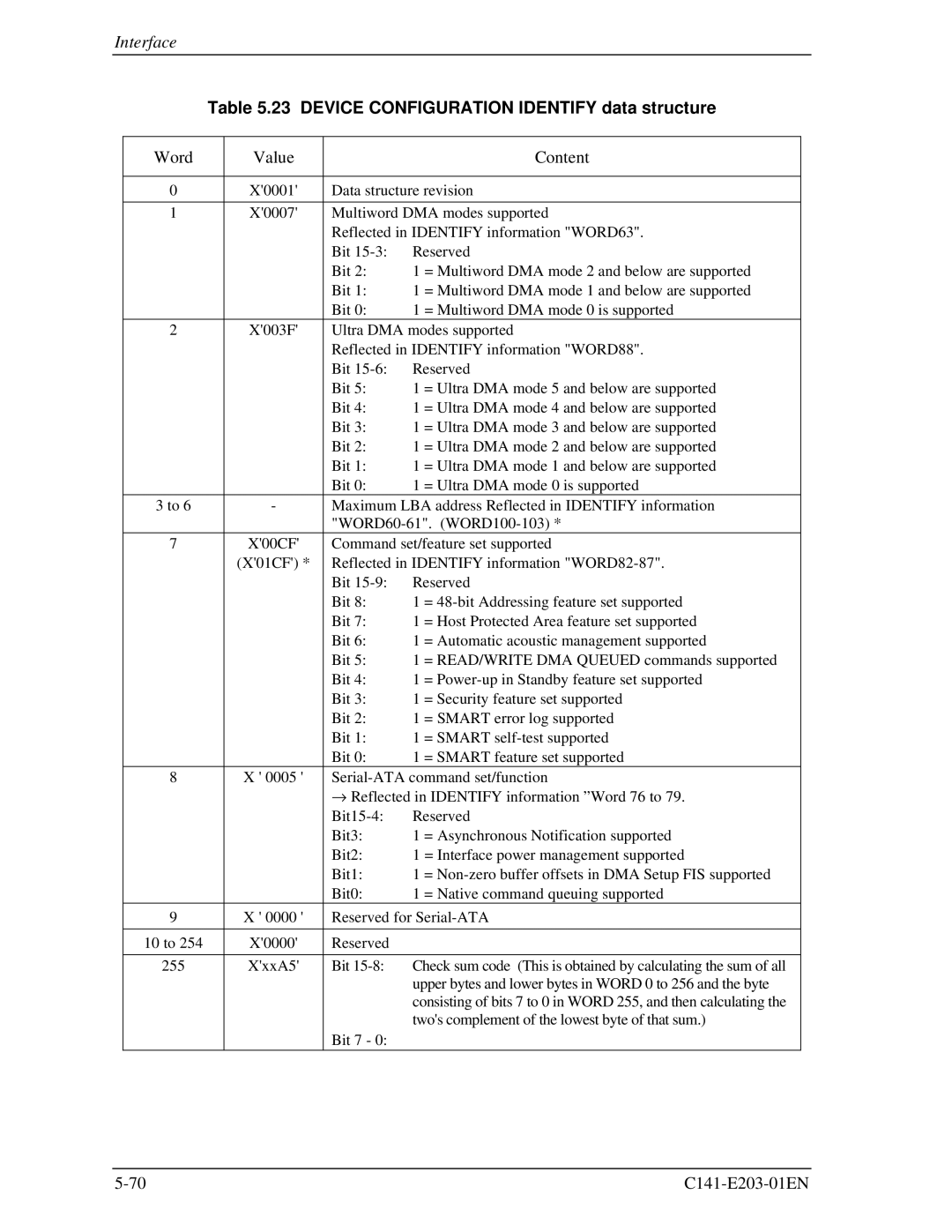
Table 5.23 DEVICE CONFIGURATION IDENTIFY data structure
Word | Value |
|
| Content |
|
|
| ||
0 | X'0001' | Data structure revision | ||
|
|
| ||
1 | X'0007' | Multiword DMA modes supported | ||
|
| Reflected in IDENTIFY information "WORD63". | ||
|
| Bit | Reserved | |
|
| Bit 2: | 1 | = Multiword DMA mode 2 and below are supported |
|
| Bit 1: | 1 | = Multiword DMA mode 1 and below are supported |
|
| Bit 0: | 1 | = Multiword DMA mode 0 is supported |
2 | X'003F' | Ultra DMA modes supported | ||
|
| Reflected in IDENTIFY information "WORD88". | ||
|
| Bit | Reserved | |
|
| Bit 5: | 1 | = Ultra DMA mode 5 and below are supported |
|
| Bit 4: | 1 | = Ultra DMA mode 4 and below are supported |
|
| Bit 3: | 1 | = Ultra DMA mode 3 and below are supported |
|
| Bit 2: | 1 | = Ultra DMA mode 2 and below are supported |
|
| Bit 1: | 1 | = Ultra DMA mode 1 and below are supported |
|
| Bit 0: | 1 | = Ultra DMA mode 0 is supported |
3 to 6 | - | Maximum LBA address Reflected in IDENTIFY information | ||
|
| |||
7 | X'00CF' | Command set/feature set supported | ||
| (X'01CF') * | Reflected in IDENTIFY information | ||
|
| Bit | Reserved | |
|
| Bit 8: | 1 | = |
|
| Bit 7: | 1 | = Host Protected Area feature set supported |
|
| Bit 6: | 1 | = Automatic acoustic management supported |
|
| Bit 5: | 1 | = READ/WRITE DMA QUEUED commands supported |
|
| Bit 4: | 1 | = |
|
| Bit 3: | 1 | = Security feature set supported |
|
| Bit 2: | 1 | = SMART error log supported |
|
| Bit 1: | 1 | = SMART |
|
| Bit 0: | 1 | = SMART feature set supported |
8 | X ' 0005 ' | |||
|
| → Reflected in IDENTIFY information ”Word 76 to 79. | ||
|
| Reserved | ||
|
| Bit3: | 1 | = Asynchronous Notification supported |
|
| Bit2: | 1 | = Interface power management supported |
|
| Bit1: | 1 | = |
|
| Bit0: | 1 | = Native command queuing supported |
9 | X ' 0000 ' | Reserved for | ||
|
|
|
|
|
10 to 254 | X'0000' | Reserved |
|
|
|
|
|
| |
255 | X'xxA5' | Bit | Check sum code (This is obtained by calculating the sum of all | |
|
|
| upper bytes and lower bytes in WORD 0 to 256 and the byte | |
|
|
| consisting of bits 7 to 0 in WORD 255, and then calculating the | |
|
|
| two's complement of the lowest byte of that sum.) | |
|
| Bit 7 - 0: |
|
|
