5.3 Host Commands
At command completion (Shadow Block Registers contents to be read)
ST |
|
|
| Status information |
| ||
|
|
|
|
|
|
|
|
DH | x | x | x |
| x |
| xx |
|
|
|
|
|
|
|
|
CH |
|
|
|
| xx |
| |
CL |
|
|
|
| xx |
| |
SN |
|
|
|
| xx |
| |
SC |
|
|
|
| xx |
| |
E |
|
|
| Error information |
| ||
|
|
|
|
|
|
|
|
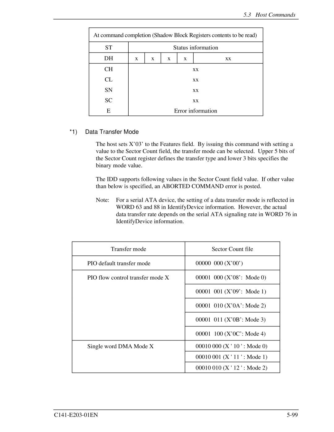
*1) Data Transfer Mode
The host sets X’03’ to the Features field. By issuing this command with setting a value to the Sector Count field, the transfer mode can be selected. Upper 5 bits of the Sector Count register defines the transfer type and lower 3 bits specifies the binary mode value.
The IDD supports following values in the Sector Count field value. If other value than below is specified, an ABORTED COMMAND error is posted.
Note: For a serial ATA device, the setting of a data transfer mode is reflected in WORD 63 and 88 in IdentifyDevice information. However, the actual data transfer rate depends on the serial ATA signaling rate in WORD 76 in IdentifyDevice information.
| Transfer mode |
| Sector Count file | |
|
|
|
|
|
• | PIO default transfer mode | 00000 | 000 | (X’00’) |
|
|
|
| |
• | PIO flow control transfer mode X | 00001 000 | (X’08’: Mode 0) | |
|
|
|
|
|
|
| 00001 | 001 | (X’09’: Mode 1) |
|
|
|
|
|
|
| 00001 | 010 | (X’0A’: Mode 2) |
|
|
|
|
|
|
| 00001 | 011 | (X’0B’: Mode 3) |
|
|
|
|
|
|
| 00001 | 100 | (X’0C’: Mode 4) |
|
|
| ||
• | Single word DMA Mode X | 00010 000 (X ' 10 ' : Mode 0) | ||
|
|
| ||
|
| 00010 001 (X ' 11 ' : Mode 1) | ||
|
|
| ||
|
| 00010 010 (X ' 12 ' : Mode 2) | ||
|
|
|
|
|