Interface
5.1.3 Electrical specifications
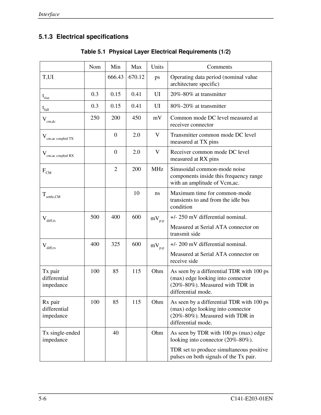
| Table 5.1 | Physical Layer Electrical Requirements (1/2) | |||||
|
|
|
|
|
|
|
|
|
| Nom |
| Min | Max | Units | Comments |
|
|
|
|
|
|
|
|
T,UI |
|
|
| 666.43 | 670.12 | ps | Operating data period (nominal value |
|
|
|
|
|
|
| architecture specific) |
|
|
|
|
|
|
|
|
trise |
| 0.3 |
| 0.15 | 0.41 | UI | |
tfall |
| 0.3 |
| 0.15 | 0.41 | UI | |
Vcm,dc |
| 250 |
| 200 | 450 | mV | Common mode DC level measured at |
|
|
|
|
|
|
| receiver connector |
Vcm,ac coupled TX |
|
|
| 0 | 2.0 | V | Transmitter common mode DC level |
|
|
|
|
|
|
| measured at TX pins |
Vcm,ac coupled RX |
|
|
| 0 | 2.0 | V | Receiver common mode DC level |
|
|
|
|
|
|
| measured at RX pins |
FCM |
|
|
| 2 | 200 | MHz | Sinusoidal |
|
|
|
|
|
|
| components inside this frequency range |
|
|
|
|
|
|
| with an amplitude of Vcm,ac. |
|
|
|
|
|
|
|
|
Tsettle,CM |
|
|
|
| 10 | ns | Maximum time for |
|
|
|
|
|
|
| transients to and from the idle bus |
|
|
|
|
|
|
| condition |
|
|
|
|
|
|
|
|
Vdiff,tx |
| 500 |
| 400 | 600 | +/- 250 mV differential nominal. | |
|
|
|
|
|
|
| Measured at Serial ATA connector on |
|
|
|
|
|
|
| transmit side |
|
|
|
|
|
|
|
|
Vdiff,rx |
| 400 |
| 325 | 600 | +/- 200 mV differential nominal. | |
|
|
|
|
|
|
| Measured at Serial ATA connector on |
|
|
|
|
|
|
| receive side |
|
|
|
|
|
|
|
|
Tx pair |
| 100 |
| 85 | 115 | Ohm | As seen by a differential TDR with 100 ps |
differential |
|
|
|
|
|
| (max) edge looking into connector |
impedance |
|
|
|
|
|
| |
|
|
|
|
|
|
| differential mode. |
|
|
|
|
|
|
|
|
Rx pair |
| 100 |
| 85 | 115 | Ohm | As seen by a differential TDR with 100 ps |
differential |
|
|
|
|
|
| (max) edge looking into connector |
impedance |
|
|
|
|
|
| |
|
|
|
|
|
|
| differential mode. |
|
|
|
|
|
|
|
|
Tx |
|
|
| 40 |
| Ohm | As seen by TDR with 100 ps (max) edge |
impedance |
|
|
|
|
|
| looking into connector |
|
|
|
|
|
|
| TDR set to produce simultaneous positive |
|
|
|
|
|
|
| pulses on both signals of the Tx pair. |
|
|
|
|
|
|
|
|