Installing a processor
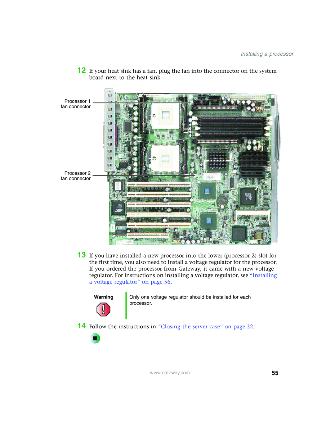
12 If your heat sink has a fan, plug the fan into the connector on the system board next to the heat sink.
Processor 1 fan connector
Processor 2 fan connector
13 If you have installed a new processor into the lower (processor 2) slot for the first time, you also need to install a voltage regulator for the processor. If you ordered the processor from Gateway, it came with a new voltage regulator. For instructions on installing a voltage regulator, see “Installing a voltage regulator” on page 56.
Warning
Only one voltage regulator should be installed for each processor.
14 Follow the instructions in “Closing the server case” on page 32.
| www.gateway.com | 55 |
|