Replace the air duct if one came with your server.
For more stability, place the server on its side.
Chapter 4: Installing Components
Closing the server case
To close the server case:
1
2 Make sure that all of the internal cables are arranged inside the case so they will not be pinched when you close the case.
3
4 Align the side panel’s top and bottom tabs into the case notches, then slide the side panel toward the back of the case until the back of the side panel is flush with the back of the case.
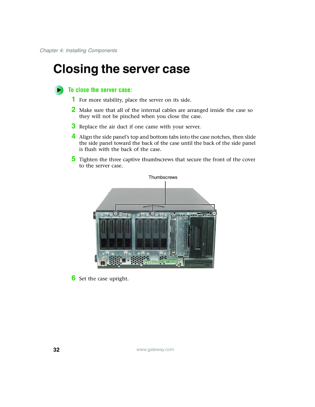
5 Tighten the three captive thumbscrews that secure the front of the cover to the server case.
Thumbscrews
6 Set the case upright.
32 | www.gateway.com |