Step 6
Use minimum 26 gauge gdvtied or 24 gauge durninurn duct in 6“ round or 3%” x 10” sk, or combination of both.
WC duct shodd be used if instig under a poured concrete slab.
N~: hd buflding code must be fofiowed in spec~g approved type and schedde of WC duct used.
5“ round duct maybe used on SHORT DU~ runs. But, note higher equivalent lengths for each 5“ dia. piece used. Don’t convert back to 5“ duct after use of 6“ round or 3%” x 10” duct
Aways use an appropriate roof or wd cap with damper. bundry type WW caps shodd NE~R be used.
pm,~m,,
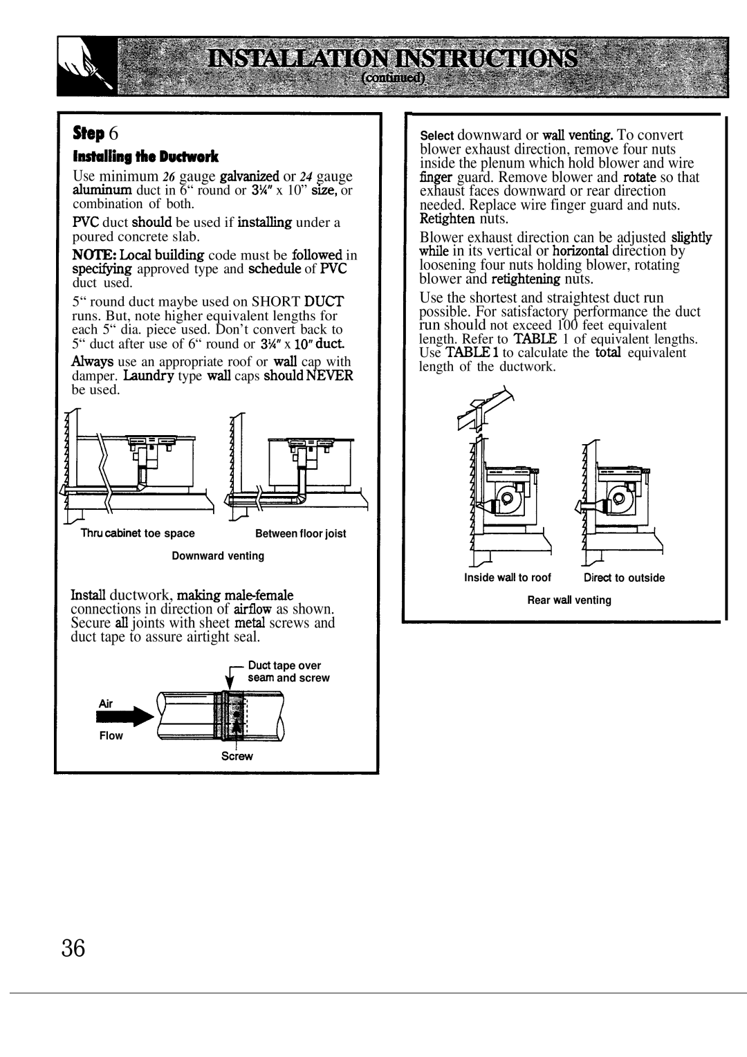
Select downward or WW ventig. To convert blower exhaust direction, remove four nuts inside the plenum which hold blower and wire tiger guard. Remove blower and rotite so that exhaust faces downward or rear direction needed. Replace wire finger guard and nuts. Retighten nuts.
Blower exhaust direction can be adjusted sfightiy wtie in its vertical or hotionti direction by loosening four nuts holding blower, rotating blower and retightetig nuts.
Use the shortest and straightest duct run possible. For satisfactory performance the duct run should not exceed 100 feet equivalent
length. Refer to T~N 1 of equivalent lengths. Use T~M 1 to calculate the toti equivalent length of the ductwork.
#
Thru ~binet toe space | Between floor joist |
Downward venting
hsti ductwork, mtig mdefemde connections in direction of tiow as shown. Secure d joints with sheet meti screws and duct tape to assure airtight seal.
Dud tape over
F sem and screw
.
h
Flow
Inside wdl to roof | Dired to outside |
Rear wdl venting
36