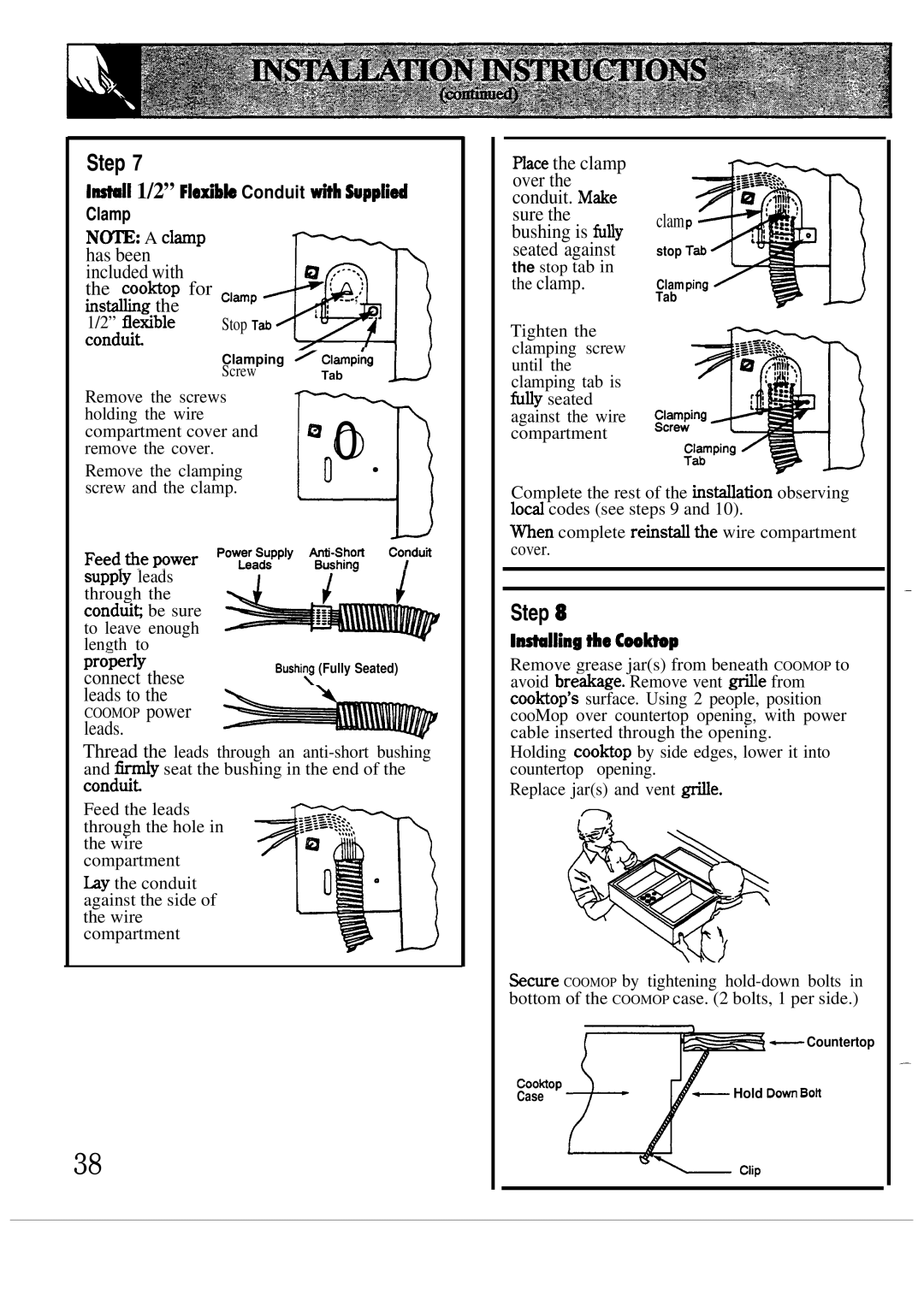
Step 7
1-11 1/2” Fletible Conduit tih Wpplied Clamp
N~: A clamp |
|
|
|
|
has been |
| Q |
| |
included with |
|
| ||
the coohop for | ~l~P |
|
| |
insfig the |
| :’ | - |
|
1/2” fletible |
|
| ||
Stop Tab |
|
| ||
conduit |
| m | ||
| Clamping ~ cl~pi~g |
| ||
| Screw | Tab | u | |
|
| |||
mace the clamp |
| |
over the |
| |
conduit. M&e |
| |
sure the | clam | |
bushing is fu~y | ||
| ||
seated against | stop | |
the stop tab in |
| |
the clamp. | Clam | |
| Tab | |
Tighten the |
| |
clamping screw |
| |
until the |
| |
clamping tab is |
|
Remove the screws holding the wire compartment cover and remove the cover.
Remove the clamping screw and the clamp.
supp~ leads through the conduic be sure to leave enough length to
connect these leads to the
COOMOP power
leads.
Q n.0
VI
Bushi~ (Fully Seated)
fufly seated |
against the wire |
compartment |
Complete the rest of the hs~ation observing lod codes (see steps 9 and 10).
men complete reinsti the wire compartment cover.
Step 8
I*lling tie Ceo*p
Remove grease jar(s) from beneath COOMOP to avoid bre&age. Remove vent de from coo~op’s surface. Using 2 people, position cooMop over countertop opening, with power cable inserted through the opening.
—
Thread the leads through an
Feed the leads through the hole in the wire compartment
by the conduit against the side of the wire compartment
38
Holding coohop by side edges, lower it into countertop opening.
Replace jar(s) and vent
%cure COOMOP by tightening
_ Countertop
coo~op | _ Hold DOW Boh |
Case |
—