TULE 1
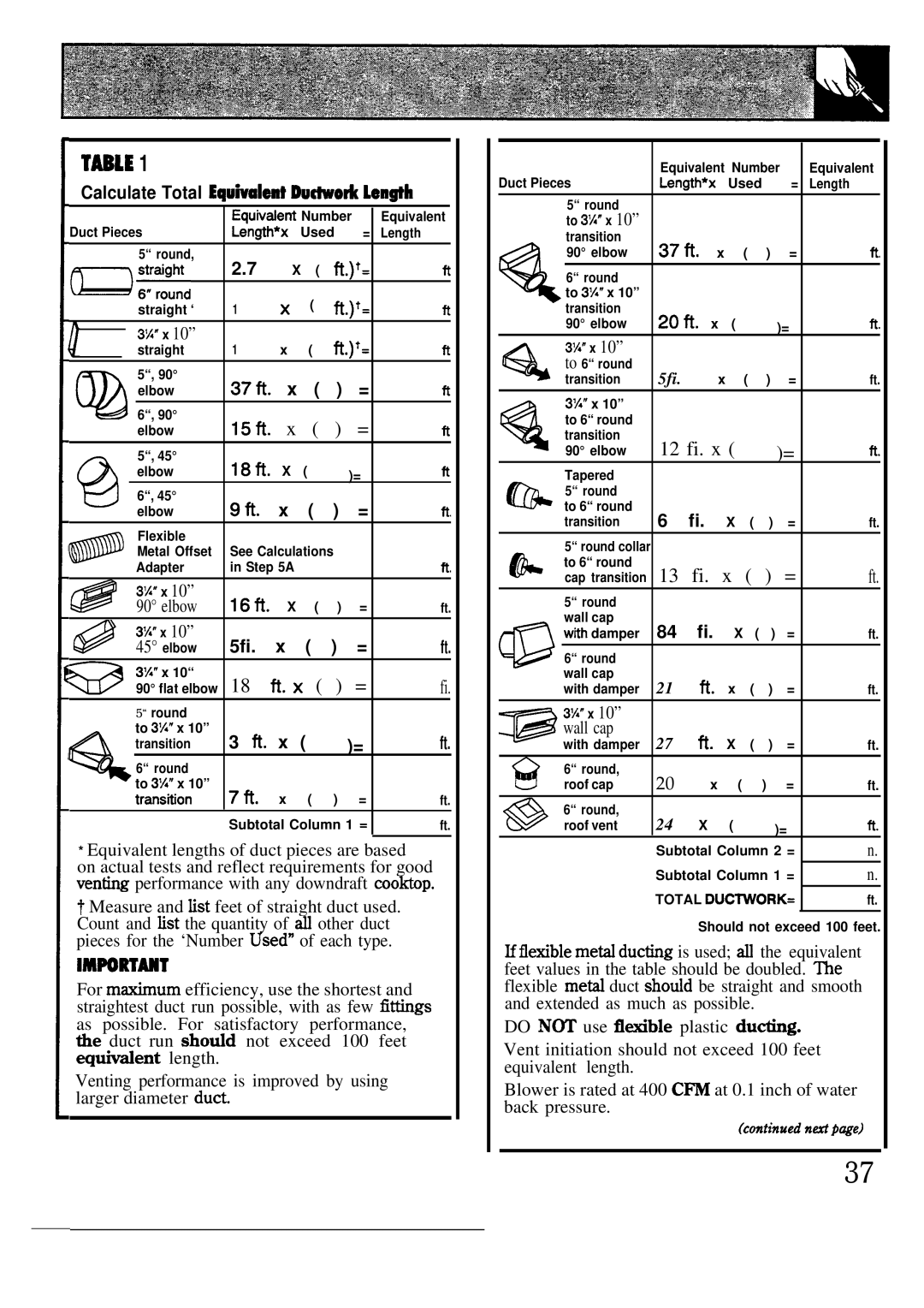
Calculate Total Equtialent DutioA Len@h
Duct Pieces | EquNdent Number | Equivalent | ||||||||||||
Length*x | Used | = | Length | |||||||||||
|
|
|
|
|
|
| 5“ round, | 2.7 | X | ( | fi.)t= |
| ||
|
|
|
|
|
|
|
| ft | ||||||
D;r:::d |
| x |
| ( | fi.)t= |
| ||||||||
|
|
|
|
|
|
| straight ‘ | 1 |
| ft | ||||
|
|
|
|
|
|
|
|
|
|
|
| |||
|
|
|
|
|
|
| 3%” x 10” | 1 |
|
|
|
|
|
|
|
|
|
|
|
|
|
|
|
|
|
|
| ||
|
|
|
|
|
|
| straight | x |
| ( | fi.)t= | ft | ||
|
|
|
|
|
|
|
|
|
|
|
|
|
|
|
|
|
|
|
|
|
| 5“, 90° | 37ti. | x |
| ( | ) | = | ft |
|
|
|
|
|
|
| elbow |
| ||||||
| @ 6“, 90° | 15fi. | x |
| ( | ) | = | ft | ||||||
|
|
|
|
|
|
| elbow |
| ||||||
|
|
|
|
|
|
| 5“, 45° | 18fi. | X |
| ( |
|
|
|
|
|
|
|
|
|
| elbow |
|
| )= | R | |||
@ |
|
|
|
| 6“, 45° | 9fi. | x |
| ( | ) | = | ft. | ||
|
|
|
| elbow |
| |||||||||
|
|
|
|
|
|
|
| |||||||
|
|
|
|
|
|
| Flexible |
|
|
|
|
|
|
|
|
|
|
|
|
|
| Metal Offset | See Calculations |
|
| ||||
|
|
|
|
|
| Adapter | in Step 5A |
|
|
|
| ft. | ||
|
|
|
|
|
| 3%” x 10” | 16fi. |
|
|
|
|
|
| |
|
|
|
|
|
| 90° elbow | X |
| ( | ) | = | ft. | ||
|
|
|
|
|
| 3%” x 10” | 5fi. | x |
| ( | ) | = | ft. | |
|
|
|
|
|
| 45° elbow |
| |||||||
|
|
|
|
|
| 3%” x 10“ | 18 | H. X | ( | ) | = | fi. | ||
@ 90° flat elbow | ||||||||||||||
|
|
|
|
|
| 5“ round |
|
|
|
|
|
|
| |
|
|
|
|
|
| to 3%” x 10” | 3 h. | x | ( |
| )= | ft. | ||
|
|
|
|
|
| transition |
| |||||||
|
|
|
|
|
| 6“ round |
|
|
|
|
|
|
| |
% to 3%” x 10” | 7R. x ( ) = |
| ||||||||||||
|
|
|
|
|
| transtion | ft. | |||||||
|
|
|
|
|
|
|
| Subtotal Column 1 = | ft. | |||||
*Equivalent lengths of duct pieces are based on actual tests and reflect requirements for good ven~ performance with any downdraft cooktop.
~Measure and fist feet of straight duct used. Count and fist the quantity of W other duct pieces for the ‘Number Used” of each type.
lMmmMT
For mfium efficiency, use the shortest and straightest duct run possible, with as few fitigs as possible. For satisfactory performance, tie duct run shotid not exceed 100 feet *tient length.
Venting performance is improved by using larger diameter duct
Duct Pieces | Equivalent Number | Equivalent | |||||||||
Length*x | Used | = |
| Length | |||||||
|
|
|
|
|
|
|
|
|
|
|
|
|
| 5“ round |
|
|
|
|
|
|
|
|
|
|
| to 3%” x 10” |
|
|
|
|
|
|
|
|
|
|
| transition | 37fi. |
|
|
|
|
|
|
| |
|
| 90° elbow | x |
| ( | ) | = |
| ft. | ||
|
| 6“ round |
|
|
|
|
|
|
|
|
|
Q to 3%” x 10” |
|
|
|
|
|
|
|
|
| ||
|
| transition | 2ofi. |
|
|
|
|
|
|
| |
|
| 90° elbow | x | ( |
|
| )= |
| fi | ||
|
| 3%” x 10” |
|
|
|
|
|
|
|
|
|
% |
| to 6“ round | 5fi. |
|
|
|
|
|
|
|
|
| transition |
| x |
| ( | ) | = |
| ft. | ||
|
| 3%” x 10” |
|
|
|
|
|
|
|
|
|
|
| to 6“ round |
|
|
|
|
|
|
|
|
|
% |
| transition | 12 fi. x ( |
|
| )= |
| fi | |||
| 90° elbow |
|
|
| |||||||
|
|
|
|
| |||||||
|
| Tapered |
|
|
|
|
|
|
|
|
|
|
| 5“ round |
|
|
|
|
|
|
|
|
|
@ to 6“ round | 6 | fi. |
|
|
|
|
|
| |||
| transition | X | ( | ) | = |
| ft. | ||||
|
| 5“ round collar |
|
|
|
|
|
|
|
|
|
& | to 6“ round | 13 fi. x ( ) = | ft. | ||||||||
| cap transition | ||||||||||
| 5“ round |
|
|
|
|
|
|
|
|
| |
| wall cap | 84 | fi. |
|
|
|
|
|
| ||
| wtih damper | X | ( | ) = |
| ft. | |||||
|
|
|
|
|
|
|
|
|
|
| |
@ | 6“ round |
|
|
|
|
|
|
|
|
| |
| wall cap | 21 |
| R. |
|
|
|
|
|
| |
| with damper |
| x | ( | ) | = |
| ft. | |||
| 3%” x 10” |
|
|
|
|
|
|
|
|
| |
| wall cap |
|
|
|
|
|
|
|
|
| |
= with damper | 27 |
| H. | X | ( | ) | = |
| ft. | ||
| 6“ round, | 20 |
|
|
|
|
|
|
|
| |
| roof cap |
| x | ( |
| ) | = |
| ft. | ||
| 6“ round, | 24 |
|
|
|
|
|
|
|
| |
| roof vent |
| X | ( |
|
| )= |
| H | ||
|
|
| Subtotal Column 2 = | n. | |||||||
|
|
| Subtotal Column 1 = | n. | |||||||
|
|
| TOTAL DUCWORK= | ft. | |||||||
|
|
|
|
|
|
|
| ||||
|
|
|
|
| Should not exceed 100 feet. | ||||||
Hflexible meti ducting is used; d the equivalent feet values in the table should be doubled. me flexible meti duct shotid be straight and smooth and extended as much as possible.
DO N~ use fl~ble plastic du~g.
Vent initiation should not exceed 100 feet equivalent length.
Blower is rated at 400 Cm at 0.1 inch of water back pressure.
(cmtinued ndpwe)
37