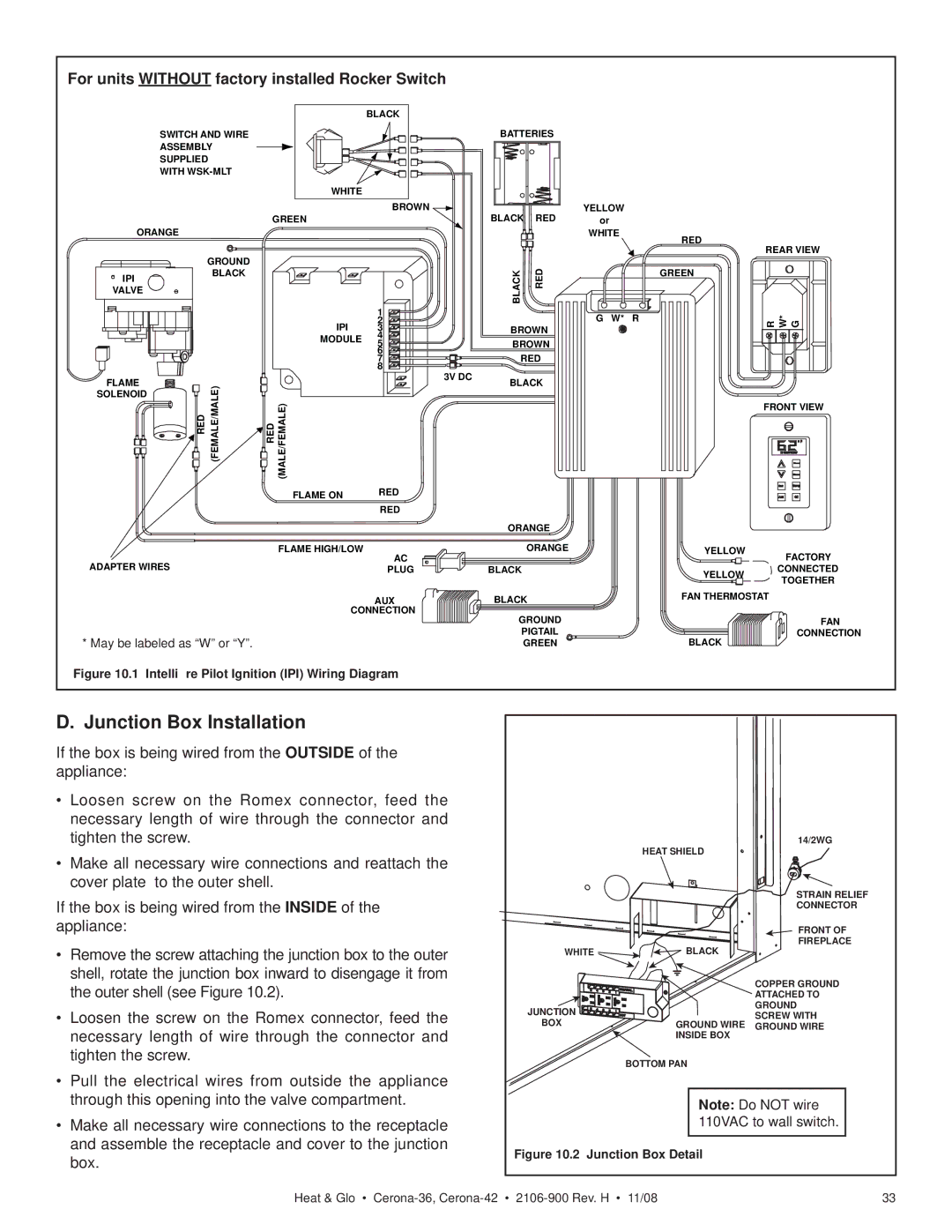
For units WITHOUT factory installed Rocker Switch
|
|
| BLACK |
|
|
|
|
SWITCH AND WIRE |
|
|
| BATTERIES |
| ||
ASSEMBLY |
|
|
|
|
|
| |
SUPPLIED |
|
|
|
|
|
|
|
WITH |
|
|
|
|
|
| |
|
| WHITE |
|
|
|
|
|
|
| GREEN | BROWN |
| BLACK | RED | YELLOW |
ORANGE |
|
|
| or | |||
|
|
|
|
|
| WHITE | |
GROUND |
|
|
| BLACK | RED |
| |
IPI | BLACK |
|
|
|
| ||
|
|
|
|
| |||
VALVE |
|
|
|
|
|
|
|
|
|
| 1 |
|
|
| G W* R |
|
| IPI | 2 |
|
|
| |
|
| 3 |
| BROWN |
| ||
|
| MODULE | 4 |
| BROWN |
| |
|
| 5 |
|
| |||
|
|
| 6 |
| RED |
| |
|
|
| 7 |
|
| ||
|
|
| 8 | 3V DC |
|
|
|
FLAME | (FEMALE/MALE) |
|
| BLACK |
| ||
RED (MALE/FEMALE) |
|
|
| ||||
RED |
|
|
|
|
| ||
SOLENOID |
|
|
|
|
|
|
|
|
| FLAME ON | RED |
|
|
|
|
|
|
| RED |
|
|
|
|
|
|
|
|
| ORANGE |
| |
|
| FLAME HIGH/LOW | AC |
|
| ORANGE |
|
ADAPTER WIRES |
|
|
|
|
|
| |
|
| PLUG |
| BLACK |
|
| |
|
|
| AUX |
| BLACK |
| |
|
| CONNECTION |
| GROUND |
| ||
|
|
|
|
|
| ||
* May be labeled as “W” or “Y”. |
|
|
| PIGTAIL |
| ||
|
|
| GREEN |
| |||
Figure 10.1 Intellifire Pilot Ignition (IPI) Wiring Diagram
RED
REAR VIEW
GREEN
G
W*
R
FRONT VIEW
YELLOW FACTORY
YELLOW CONNECTED TOGETHER
FAN THERMOSTAT
FAN
CONNECTION
BLACK
D. Junction Box Installation |
|
|
| ||
If the box is being wired from the OUTSIDE of the |
|
|
| ||
appliance: |
|
|
| ||
• Loosen screw on the Romex connector, feed the |
|
|
| ||
| necessary length of wire through the connector and |
|
|
| |
| tighten the screw. |
| HEAT SHIELD | 14/2WG | |
• | Make all necessary wire connections and reattach the |
|
| ||
|
|
| |||
| cover plate to the outer shell. |
|
| STRAIN RELIEF | |
If the box is being wired from the INSIDE of the |
|
| |||
|
| CONNECTOR | |||
appliance: |
|
| FRONT OF | ||
• | Remove the screw attaching the junction box to the outer | WHITE | BLACK | FIREPLACE | |
| |||||
| shell, rotate the junction box inward to disengage it from |
|
| COPPER GROUND | |
| the outer shell (see Figure 10.2). |
|
| ||
|
|
| ATTACHED TO | ||
• Loosen the screw on the Romex connector, feed the | JUNCTION |
| GROUND | ||
| SCREW WITH | ||||
BOX | GROUND WIRE | ||||
GROUND WIRE | |||||
| necessary length of wire through the connector and |
| |||
|
| INSIDE BOX |
| ||
| tighten the screw. |
| BOTTOM PAN |
| |
|
|
|
| ||
• Pull the electrical wires from outside the appliance |
|
|
| ||
| through this opening into the valve compartment. |
| Note: Do NOT wire | ||
• | Make all necessary wire connections to the receptacle |
| 110VAC to wall switch. | ||
| and assemble the receptacle and cover to the junction | Figure 10.2 Junction Box Detail |
| ||
| box. |
| |||
|
|
|
| ||
| Heat & Glo • | 33 | |||