11 Finishing
A. Mantel Projections
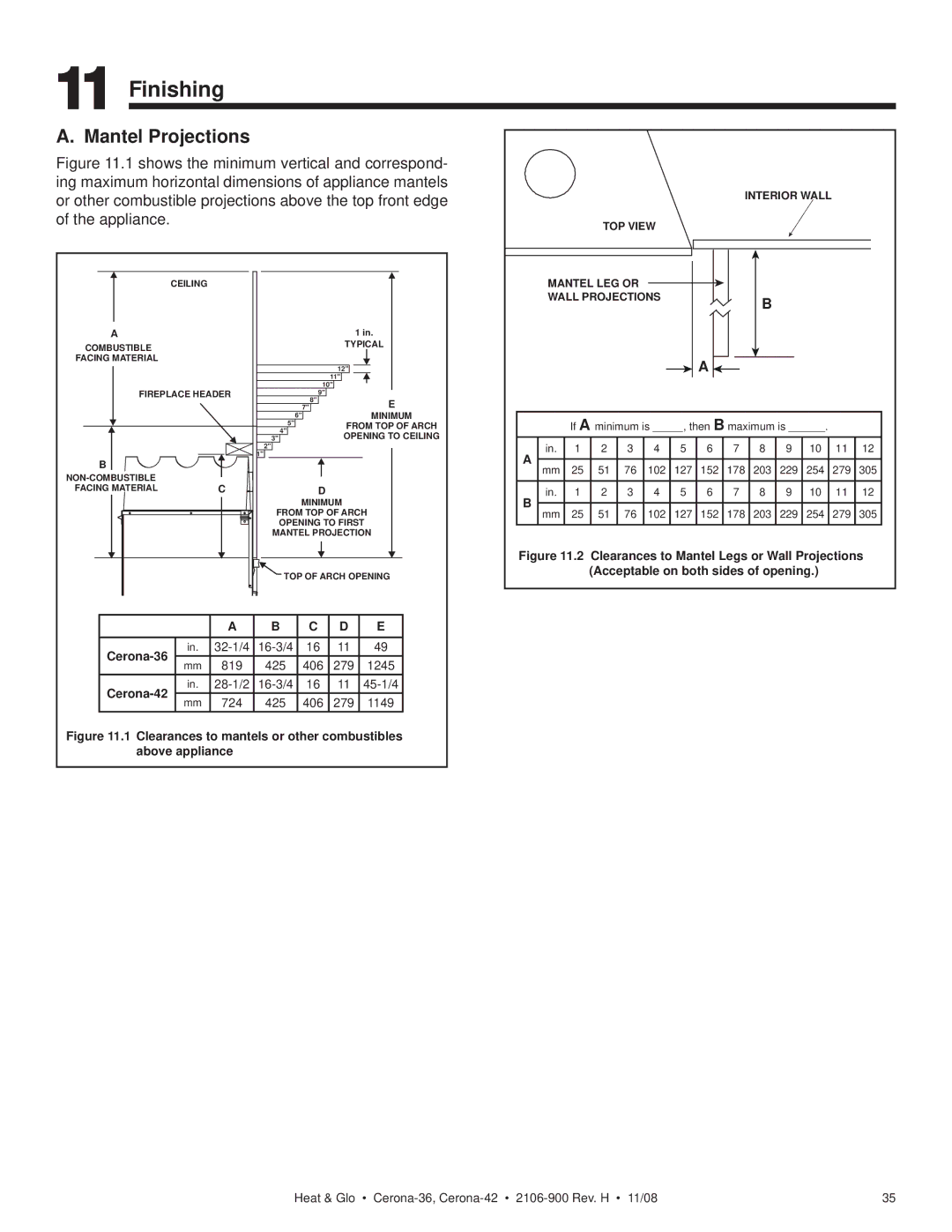
Figure 11.1 shows the minimum vertical and correspond- ing maximum horizontal dimensions of appliance mantels or other combustible projections above the top front edge of the appliance.
|
| CEILING | |
|
| 1 in. | |
A | |||
COMBUSTIBLE | TYPICAL | ||
FACING MATERIAL |
|
| |
TOP VIEW
MANTEL LEG OR WALL PROJECTIONS
INTERIOR WALL
B
|
|
|
|
| 12" |
| |
|
|
|
|
| 11" |
| |
|
|
|
| 10" |
| ||
FIREPLACE HEADER |
| 9" |
|
| |||
|
|
|
| 8" |
| E | |
|
|
|
| 7" |
| ||
|
|
| 6" |
|
| MINIMUM | |
|
|
| 5" |
| FROM TOP OF ARCH | ||
|
|
| 4" |
| |||
|
|
|
| OPENING TO CEILING | |||
|
|
| 3" |
| |||
|
|
| 2" |
|
|
| |
B |
|
| 1" |
|
|
| |
|
|
|
|
|
| ||
|
|
|
|
|
| ||
FACING MATERIAL |
| C |
| D |
|
| |
|
|
| MINIMUM |
| |||
|
|
| FROM TOP OF ARCH | ||||
|
|
| OPENING TO FIRST | ||||
|
|
| MANTEL PROJECTION | ||||
|
|
| TOP OF ARCH OPENING | ||||
|
| A | B | C | D | E | |
in. | 16 | 11 | 49 | ||||
mm | 819 | 425 | 406 | 279 | 1245 | ||
| |||||||
| in. | 16 | 11 | ||||
mm | 724 | 425 | 406 | 279 | 1149 | ||
| |||||||
Figure 11.1 Clearances to mantels or other combustibles above appliance
A ![]()
If A minimum is _____, then B maximum is ______.
in. | 1 | 2 | 3 | 4 | 5 | 6 | 7 | 8 | 9 | 10 | 11 | 12 |
A
mm 25 51 76 102 127 152 178 203 229 254 279 305
in. | 1 | 2 | 3 | 4 | 5 | 6 | 7 | 8 | 9 | 10 | 11 | 12 |
B
mm 25 51 76 102 127 152 178 203 229 254 279 305
Figure 11.2 Clearances to Mantel Legs or Wall Projections (Acceptable on both sides of opening.)
Heat & Glo • | 35 |