Service Parts |
|
|
|
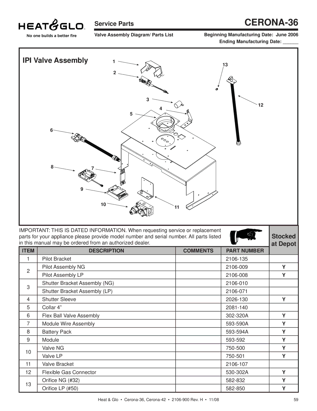
Valve Assembly Diagram/ Parts List | Beginning Manufacturing Date: June 2006 |
| Ending Manufacturing Date: ______ |
IPI Valve Assembly |
| 1 |
| 13 |
|
|
|
| |
|
| 2 |
|
|
|
|
| 3 | 12 |
|
|
| 4 | |
|
|
|
| |
|
|
| 5 |
|
6 |
|
|
|
|
8 | 7 |
|
|
|
9 |
|
|
|
|
| 10 |
|
| 11 |
|
|
|
|
IMPORTANT: THIS IS DATED INFORMATION. When requesting service or replacement |
| Stocked | ||
parts for your appliance please provide model number and serial number. All parts listed |
| |||
in this manual may be ordered from an authorized dealer. |
|
| at Depot | |
ITEM | DESCRIPTION | COMMENTS | PART NUMBER |
|
1 | Pilot Bracket |
|
| |
2 | Pilot Assembly NG |
| Y | |
Pilot Assembly LP |
| Y | ||
|
| |||
3 | Shutter Bracket Assembly (NG) |
|
| |
Shutter Bracket Assembly (LP) |
|
| ||
|
|
| ||
4 | Shutter Sleeve |
| Y | |
5 | Collar 4” |
|
| |
6 | Flex Ball Valve Assembly |
| Y | |
7 | Module Wire Assembly |
| Y | |
8 | Battery Pack |
| Y | |
9 | Module |
| Y | |
10 | Valve NG |
| Y | |
Valve LP |
| Y | ||
|
| |||
11 | Valve Bracket |
|
| |
12 | Flexible Gas Connector |
| Y | |
13 | Orifice NG (#32) |
| Y | |
Orifice LP (#50) |
| Y | ||
|
| |||
Heat & Glo • | 59 |