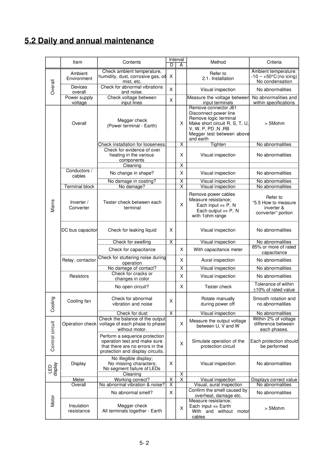
5.2 Daily and annual maintenance
| Item | Contents | Interval | Method | Criteria | |
|
|
| D | A |
|
|
|
|
|
|
|
|
|
| Ambient | Check ambient temperature, |
|
| Refer to | Ambient temperature: |
| humidity, dust, corrosive gas, oil | X |
| |||
Overall | Environment |
| 2.1. Installation | |||
and noise. | X |
| No abnormalities | |||
overall |
| Visual inspection | ||||
|
| mist, etc. |
|
|
| No condensation |
| Devices | Check for abnormal vibrations |
|
|
|
|
| Power supply | Check voltage between | X |
| Measure the voltage between | No abnormalities and |
| voltage | input lines |
| input terminals | within specifications | |
|
|
| ||||
|
|
|
|
| Remove connector J61 |
|
|
|
|
|
| Disconnect power line |
|
|
| Megger check |
|
| Remove logic terminal |
|
| Overall |
| X | Make short circuit R, S, T, U, | > 5Mohm | |
| (Power terminal - Earth) |
| ||||
|
|
|
| V, W, P, PD ,N ,RB |
| |
|
|
|
|
|
| |
|
|
|
|
| Megger test between above |
|
|
|
|
|
| and earth |
|
|
| Check installation for looseness. |
| X | Tighten | No abnormalities |
|
| Check for evidence of over |
|
|
|
|
|
| heating in the various |
| X | Visual inspection | No abnormalities |
|
| components |
|
|
|
|
| Conductors / | Cleaning |
| X |
|
|
| No change in shape? |
| X | Visual inspection | No abnormalities | |
| cables |
| ||||
| No damage in coating? |
| X | Visual inspection | No abnormalities | |
|
|
| ||||
| Terminal block | No damage? |
| X | Visual inspection | No abnormalities |
|
|
|
|
| Remove power cables | Refer to |
Mains | Inverter / | Tester check between each |
|
| Measure resistance; | |
| X | “5.5 How to measure | ||||
| Each output ⇔ P, N | |||||
| Converter | terminal |
| Each input ⇔ P, N | inverter & | |
|
|
|
|
| with 1ohm range | converter“ portion |
|
|
|
|
|
| |
| DC bus capacitor | Check for leaking liquid | X |
| Visual inspection | No abnormalities |
|
| Check for swelling | X |
| Visual inspection | No abnormalities |
|
| Check for capacitance |
| X | With capacitance meter | 85% or more of rated |
|
|
| capacitance | |||
|
| Check for stuttering noise during |
|
|
| |
| Relay, contactor |
| X | Aural inspection | No abnormalities | |
|
| operation |
|
|
|
|
|
| No damage of contact? |
| X | Visual inspection | No abnormalities |
| Resistors | Check for cracks or |
| X | Visual inspection | No abnormalities |
| changes in color |
| ||||
|
|
|
|
| Tolerance of within | |
|
| No open circuit? |
| X | Tester check | |
|
|
| ±10% of rated value | |||
|
|
|
|
|
| |
Cooling | Cooling fan | Check for abnormal | X |
| Rotate manually | Smooth rotation and |
vibration and noise |
| during power off | no abnormalities | |||
|
| |||||
|
|
|
| |||
|
| Check for dust | X |
| Visual inspection | No abnormalities |
circuit |
| Check the balance of the output |
|
| Measure the output voltage | Within 2% of voltage |
Operation check | voltage of each phase to phase |
| X | difference between | ||
| between U, V and W | |||||
|
| |||||
|
| without motor. |
|
| each phases. | |
|
|
|
|
| ||
Control |
| Perform a sequence protection |
|
|
|
|
| operation test and make sure |
| X | Simulate operation of the | Each protection should | |
|
| that there are no errors in the |
| protection circuit | be performed | |
|
|
|
| |||
|
| protection and display circuits. |
|
|
|
|
|
|
|
|
|
|
|
|
| No illegible display; |
|
|
|
|
LED display | Display | No missing characters; | X | X | Visual inspection | No abnormalities |
| Cleaning |
|
|
| ||
|
| No segment failure of LEDs |
|
|
|
|
| Meter | Working correct? | X | X | Visual inspection | Displays correct value |
| Overall | No abnormal vibration & noise? | X |
| Visual, aural inspection | No abnormalities |
|
| No abnormal smell? | X |
| Confirm the smell caused by | No abnormalities |
Motor |
|
| overheat, damage etc. | |||
|
|
|
|
| ||
Insulation | Megger check |
|
| Measure resistance; |
| |
|
|
|
| |||
|
| X | Each input ⇔ Earth | > 5Mohm | ||
| resistance | All terminals together - Earth |
| With and without motor | ||
|
|
|
| |||
|
|
|
|
| cables |
|
5- 2