Maintenance and Service Guide
Product notice
Iii
About This Book
Iv About This Book
Table of contents
Page
Preparation for disassembly Vii
Removal and replacement procedures Tower TWR
Page
Computer Setup F10 Utility 180
Password security and resetting Cmos 250
Appendix C Specifications 275
Xii
Tower TWR
Standard configuration features
Standard configuration features
Small Form Factor SFF Ultra-slim Desktop Usdt
Product features
Tower TWR front panel components
Small Form Factor SFF front panel components
Ultra-slim Desktop Usdt front panel components
Ultra-slim Desktop Usdt front panel components
Tower TWR rear panel components
Small Form Factor SFF rear panel components
Small Form Factor SFF rear panel components
Serial number location
Ultra-slim Desktop Usdt rear panel components
Serial number location
Tower TWR Small Form Factor SFF
Ultra-slim Desktop Usdt
Activating the Windows operating system
Activating and customizing the software in Windows
Customizing the monitor display
Downloading Windows 7 updates
Installing or upgrading device drivers
Click Settings Change PC Settings
Downloading Windows 8 updates
Illustrated parts catalog
Tower TWR chassis spare parts
Computer major components
Tower TWR chassis spare parts
Cables
Misc parts
Optical drive
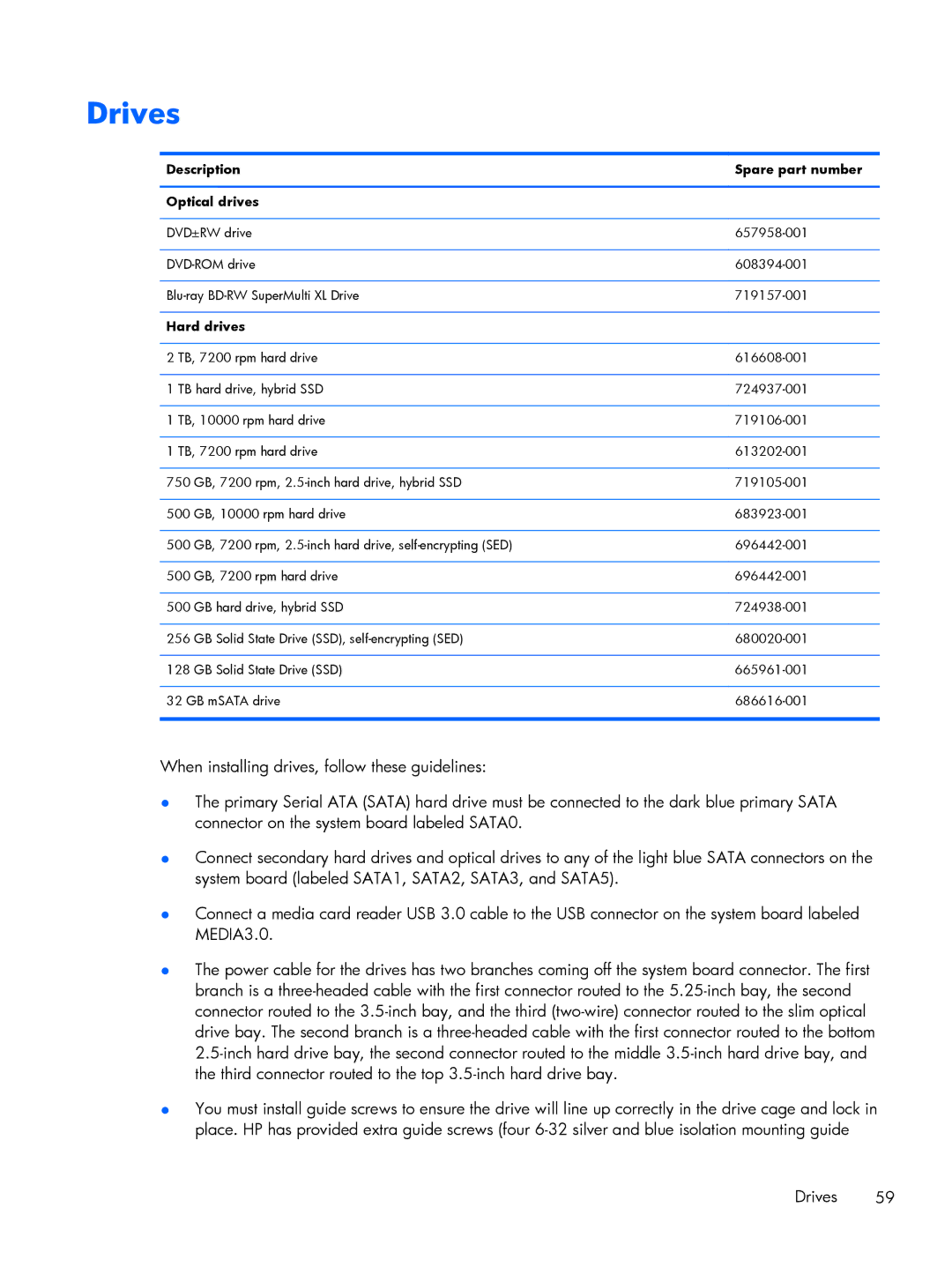
Drives
Item Description Spare part number Keyboard
Description Spare part number Hard drive
Spare part Description Number
Misc boards
Sequential part number listing
Description Spare part number
Illustrated parts catalog
Tower TWR chassis spare parts
Small Form Factor SFF chassis spare parts
Item Description Spare part number
Chassis stand
Fan duct
Rubber foot
Drives
Sequential part number listing
Small Form Factor SFF chassis spare parts
Illustrated parts catalog
AC adapter
Description Spare part number Access panel
Ultra-Slim Desktop Usdt chassis spare parts
Stand
689372-001
Misc parts
Drives
Misc boards
Illustrated parts catalog
Electrostatic discharge information
Relative Humidity Event 55% 40% 10%
Generating static
Preventing electrostatic damage to equipment
Static Shielding Protection Levels
Personal grounding methods and equipment
Grounding the work area
Recommended materials and equipment
Operating guidelines
Routine care
General cleaning safety precautions
Cleaning the Computer Case
Cleaning the keyboard
Power supply fan
Service considerations
Cleaning the monitor
Cleaning the mouse
Hard Drives
Cables and connectors
Tools and software Requirements
Screws
Sata hard drives
Lithium coin cell battery
Serial ATA Hard Drive Characteristics
Sata data cable
Sata hard drive cables
Smart ATA drives
Cable management
Preparation for disassembly
Removal and replacement procedures Tower TWR
Description Spare part number Access panel 732748-001
Access panel
Front bezel security
Front bezel
Bezel blanks
Page
Populating Dimm sockets
Memory
DIMMs
DDR3-SDRAM DIMMs
Installing DIMMs
Page
Expansion cards
Page
Page
Page
System board connections
System Board Connector System Board Label Color Component
BAT
Hard drives
Drives
Description Spare part number Optical drives
Guide Screw Device
Drive positions
Removing a 5.25-inch drive
Installing a 5.25-inch drive
Page
Removing a 3.5-inch device
Page
Installing a 3.5-inch device
Removing a slim optical drive
Installing a slim optical drive
Page
Removing a 3.5-inch or 2.5-inch hard drive
Installing a 3.5-inch or 2.5-inch hard drive
Page
Page
Page
Page
Media
Front I/O assembly
Description Spare part number Front I/O assembly 732750-001
Power switch/LED assembly
Page
Description Spare part number Fan sink 727142-001
Fan sink
Page
Intel Core i5 processors
Processor
Description Spare part number Intel Core i7 processor
Description Spare part number Speaker 645330-001
Speaker
Description Spare part number Solenoid lock 641498-001
Smart Cover Lock solenoid lock
Hlock
Page
Description Spare part number Hood sensor 638816-001
Hood sensor
Description Spare part number Fan 727135-001
Fan
Page
PWR Pwrcpu Pwrcmd
Power supply
Page
Page
System board and PCI expansion slot daughter card
Page
Removal and replacement procedures Small Form Factor SFF
Description Spare part number Access panel 732760-001
Front bezel 732757-001 Optical drive bezel blank 732769-001
Front bezel security
Page
Bezel blanks
Memory
Installing DIMMs
Page
Expansion card
Page
Page
Page
SATAPWR0
108 Removal and replacement procedures Small Form Factor SFF
Page
Drive positions
Removing a 3.5-inch device
Installing a 3.5-inch device
Page
Removing a slim optical drive
Installing a slim optical drive
Removing and replacing a 3.5-inch hard drive
Page
Page
Removing a 2.5-inch hard drive
Installing a 2.5-inch hard drive
Page
Pwrcpu Pwrcmd PWR
Page
Page
Description Spare part number Fan duct 727145-001
Fan duct
Description Spare part number Solenoid lock 732772-001
Hlock
Smart Cover Lock solenoid lock 127
Hood sensor
Cable routing
Description Spare part number Front I/O assembly 732755-001
Page
Power switch assembly
Page
Description Spare part number Speaker 727149-001
Description Spare part number Fan sink 727150-001
Processor
Page
System board
Page
Changing from desktop to tower configuration
Removal and replacement procedures Ultra-slim Desktop Usdt
Description Spare part number Access panel 732763-001
Description Spare part number Front bezel 732764-001
Front bezel security
Bezel blank
Hlock
DDR3-SDRAM SODIMMs
SODIMMs
Description System Board Label Socket Color
Populating Sodimm sockets
Installing SODIMMs
Description Spare part number Front fan 732765-001
Front fan
Removing the optical drive
Optical drive
Preparing the new optical drive
Installing the new optical drive
Remove the optical drive Removing the optical drive on
Hard drive
Page
Description Spare part number Speaker 689384-001
Description Spare part number Heat sink 587456-001
Heat sink
Page
Processor
Smart Cover Lock solenoid lock
Page
Page
Smart Cover Lock solenoid lock 163
Description Spare part number Drive cage 732761-001
Drive cage
Hood sensor
Description Spare part number Card reader Xxxxxx-001
Card reader
Page
Wlan module
Graphics board
Description Spare part number Power switch 732767-001
Power switch
System board
Page
Description Spare part number Rear fan 732766-001
Rear fan
Antennas
Page
Page
Page
Changing from desktop to tower configuration
Description Spare part number Port cover 588981-001
Power supply, external
Usdt chassis uses an external power supply Port cover
Port cover
Computer Setup F10 Utilities
Computer Setup F10 Utility
Using Computer Setup F10 Utilities
Computer Setup F10 Utility
Computer Setup-File
Computer Setup-Storage
Storage Options Sata Emulation
Removable Media Boot
DPS Self-Test
Boot Order
Shortcut to Temporarily Override Boot Order
Computer Setup-Security
Slot Security
Network Boot
Device Security
USB Security
Security
Virtualization Technology Directed I/O
System Security
DriveLock Security
Secure Boot
Management
Computer Setup-Power
Option Description OS Power
Thermal
Hardware Power
Option Heading Power-On Options
Computer Setup-Advanced
Device Options
Bios Power-On
Onboard Devices
Bus Options
AMT Configuration
Recovering the Configuration Settings
VGA Configuration
Safety and comfort Before you call for technical support
Troubleshooting without diagnostics
Refer to Helpful hints on page 197 in this guide
Helpful hints
Page
Select Control Panel
Solving general problems
Solving general problems
Computer date and time display is incorrect Cause Solution
Poor performance Cause Solution
200 Troubleshooting without diagnostics
There is no sound or sound volume is too low Cause Solution
Cannot remove computer cover or access panel Cause Solution
Under Windows System, click Run
Go to Start All Programs Accessories
Run
All apps icon
202 Troubleshooting without diagnostics
Power supply shuts down intermittently Cause Solution
Solving power problems
204 Troubleshooting without diagnostics
Solving hard drive problems
Storage Boot Order list
206 Troubleshooting without diagnostics
Advanced Power-On Options
Nonsystem disk/NTLDR missing message Cause Solution
Computer seems to be locked up Cause Solution
Device Configuration
Can not write to the media card Cause Solution
Solving media card reader problems
208 Troubleshooting without diagnostics
Solving media card reader problems 209
Select Adjust screen resolution
Solving display problems
210 Troubleshooting without diagnostics
Blank screen no video Cause Solution
Solving display problems
Select ImageControl/ Horizontal Position or Vertical
212 Troubleshooting without diagnostics
Dim characters Cause Solution
Image is not centered Cause Solution
Out of Range displays on screen Cause Solution
Certain typed symbols do not appear correct Cause Solution
214 Troubleshooting without diagnostics
Device Security System Audio
Solving audio problems
Sound cuts in and out Cause Solution
Control Panel, and then select Device Manager
216 Troubleshooting without diagnostics
Line-in jack is not functioning properly Cause Solution
Control Panel , and then select Device Manager
Solving printer problems
Printer will not print Cause Solution
218 Troubleshooting without diagnostics
Printer will not turn on Cause Solution
Printer prints garbled information Cause Solution
Solving keyboard and mouse problems 219
Solving keyboard and mouse problems
Enter
220 Troubleshooting without diagnostics
Security USB Security
Solving Hardware Installation Problems
Solving Hardware Installation Problems 221
Computer will not start Cause Solution
222 Troubleshooting without diagnostics
Wake-on-LAN feature is not functioning Cause Solution
Solving Network Problems
224 Troubleshooting without diagnostics
Manager
Network status link light never flashes Cause Solution
Diagnostics reports a failure Cause Solution
226 Troubleshooting without diagnostics
New network card will not boot Cause Solution
Solving memory problems
Insufficient memory error during operation Cause Solution
228 Troubleshooting without diagnostics
Out of memory error Cause Solution
Memory count during Post is wrong Cause Solution
Cause Solution
Solving processor problems
Poor performance is experienced Cause Solution
Storage Boot Order
Solving CD-ROM and DVD problems
230 Troubleshooting without diagnostics
Security Network Boot
Cannot eject compact disc tray-load unit Cause Solution
Movie will not play in the DVD drive Cause Solution
System will not boot from USB flash drive Cause Solution
Solving USB flash drive problems
232 Troubleshooting without diagnostics
USB flash drive not found identified Cause Solution
Unable to connect to the Internet Cause Solution
Solving front panel component problems
Solving Internet access problems
Solving front panel component problems 233
Click Internet Options
234 Troubleshooting without diagnostics
Select Start Control Panel
ROM issue Post error has occurred
Solving software problems
System files may be damaged
236 Troubleshooting without diagnostics
Post error messages
Post numeric codes and text messages
Post error messages
Post numeric codes and text messages
Verify monitor is attached and turned
Replace diskette drive
Save Changes and Exit. Reenter
Under Storage DPS Self-test
Change Storage Storage Options
Sata Emulation to IDE, and select File
Post numeric codes and text messages
If the error persists, update to the latest
Bios version and ME firmware version
Activity Beeps Possible cause Recommended action
Is not spinning, make sure the fans cable is
Pause. Beeps stop after fifth Remove a Dimm module
Once a bad card is identified, remove
Cmos
Resetting the password jumper
Clearing and resetting the Cmos
Page
How to access and run HP PC Hardware Diagnostics Uefi
Why run HP PC Hardware Diagnostics Uefi
Downloading HP PC Hardware Diagnostics to a USB device
System backup and recovery
Backing up, restoring, and recovering in Windows
Creating recovery media and backups
Using Windows 8 Refresh
Restoring and recovering using Windows 8 tools
Using Windows 8 Reset
Follow the on-screen instructions System backup and recovery
Select Reset Follow the on-screen instructions to continue
Page
Creating recovery media
Click All Programs
To create the Windows DVD
Creating recovery discs
Follow the on-screen instructions to set up your backup
System Restore
System Recovery when Windows is responding
System Recovery
System Recovery when Windows is not responding
Page
Select Install now
Battery replacement
Type
Page
General requirements
Japanese power cord requirements
Country Accrediting Agency
274 Appendix B Power cord set requirements
Country-specific requirements
TWR specifications
TWR specifications
Rated Input Current
SFF specifications
Appendix C Specifications
Usdt specifications
TWR, spare part number USDT, spare part number Index
Index
154 Usdt removal Hard drive 2.5-inch
Driver Recovery DVD
Drive rail Usdt removal
Spare part numbers
147 Usdt optical drive 153
Keyboard Cleaning Spare part numbers Keyboard problems
Usdt Wlan tuner module
Daughter card TWR power supply TWR power switch assembly
TWR fan TWR fan sink TWR front USB panel TWR hood sensor
TWR solenoid lock TWR speaker TWR system board
Number Usdt spare part number 160
107 Front I/O assembly, spare part Replacement 160
146 Power supply removal Solid-state drive, spare part
System board, spare part
Tower conversion SFF
Windows Backing up information 265 Backup and recovery