V200R001
Huawei
BOM31010868
Manual Version T2-080168-20011213-C-1.5
About This Manual
Contents
Key 1, Key
Format Description Key
Bracket, e.g. Enter , Tab , Backspace , or a
Key 1 + Key
Action Description
Symbol
Huawei
Security Configuration SC
II. IKE features
Configuration of IKE
Creating IKE Security Policy
IKE Configuration Task List
Select Authentication Algorithm
No IKE security policy is created by default
Select Encryption Algorithm
Set Pre-shared Key
Select Hashing Algorithm
Select DH Group ID
Show IKE SA parameter Quidway# show crypto ike sa
Set Lifetime of IKE Association SA
Show IKE security policy Quidway# show crypto ike policy
Networking requirements
III. Configuration procedure
II. Networking diagram
Problem 1 Invalid user ID information
VPN Configuration VPN
Table of Contents
VPN Overview
VPN features
Classification of IP VPN
According to operation mode
III. According to service purpose
II. According to the layer where the tunnel is
IV. According to networking model
Brief induction to Vpdn
Configuration of L2TP
Brief Introduction to L2TP Protocol
Overview of Vpdn
2 L2TP Protocol
III. Method to realize Vpdn
Tunnel and session
III. Two typical L2TP tunnel modes
II. Control message and data message
Call setup flow of L2TP channel is shown in the following
IV. Call setup flow of L2TP tunnel
Figure VPN-2-3Call setup flow of L2TP channel
Features of L2TP protocol
Configuring L2TP
1 L2TP Configuration Task List
Configuring at LAC Side
II. Create Vpdn group
Disable Vpdn to run by default
Table VPN-2-4L2TP attribute table
Configuring at LNS Side
Disable Vpdn running by default
IV. Set the connection request to originate L2TP channel
No accept dialin
III. Create/delete virtual interface template
No vpdn group group-number
Accept dialin l2tp virtual-template virtual
Optional configuration
III. Force local end to perform Chap authentication
Set local name of channel
Set domain name delimiter and search sequence
Local end does not perform Chap authentication by default
LCP does not renegotiate by default
IV. LNS forces LCP to renegotiate
Disable hiding AV pairs by default
VII. Enable/disable hiding AV pairs
VIII. Force to disconnect tunnel
Monitoring and Maintenance of L2TP
Networking requirement
Typical Configuration of L2TP
Show l2tp session command domain
NAS-Initialized VPN
III. Configuration procedure
Client-Initialized VPN
Figure VPN-2-5Networking diagram of Client-Initialized VPN
Single User Interconnects Headquarters via Router
Chapter
Fault Diagnosis of L2TP
Configuration of GRE
Brief Introduction to GRE Protocol
Brief introduction to the protocol
Figure VPN-3-2Format of transmission message in the tunnel
II. Applicable range
GRE Configuration Task List
Configuring GRE
Setting the Source Address of Tunnel Interface
Setting the Destination Address of Tunnel Interface
Creating Virtual Tunnel Interface
Setting Tunnel Interface to Check with Check Sum
Setting the Network Address of Tunnel Interface
Setting the Encapsulation Mode of Tunnel Interface Message
Setting the Identification Key Word of Tunnel Interface
Monitoring and Maintenance of GRE
Disable tunnel interface to check with check sum by default
Show interface tunnel tunnel-number
Figure VPN-3-6Networking diagram of GRE application
Typical Configuration of GRE
Chapter
Troubleshooting GRE
Reliability Configuration LC
Configuration of Hsrp
Configuration of Backup Center
Configuration Task List
Configuration of Backup Center
Backup Center Overview
Configuring the Backup Center
Backup logic-channel logic-channel
No backup delay
Configuring Routes for Main and Backup Interfaces
Backup state-down number
Backup state-up interval-time
An Example of Multiple Backup Interfaces
Monitoring and Maintaining of Backup Center
Typical Configuration of Backup Center
An example of Backup Between Interfaces
Chapter
Chapter
Hsrp Overview
Configuration of Hsrp
Starting Hsrp Function
Configuring Hsrp
Standby group-number preempt
Setting Router’s Priority in Hsrp Hot Standby Group
Setting Router’s Preemption Mode in Hsrp Standby Group
Setting Hsrp Authorization Word
Monitoring the Specified Interface
Setting Hsrp Timer
Table LC-2-4Set Hsrp authorization word
Standby group-numberauthentication string
Using Actual Interface MAC Address
Modifying Virtual MAC Address
Table LC-2-6Monitor the specified interface
Show relevant Hsrp information Quidway# show standby
Typical Configurations of Hsrp
An example for single hot standby group configuration
Monitoring and Maintaining Hsrp
202.38.160.111
An example for setting Hsrp to monitor a specified interface
An example for multiple hot standby groups configuration
Fault Diagnosis and Troubleshooting of Hsrp
QoS Configuration QC
CAR Configuration Example
Configure CAR Rules Based on the MAC Address
Apply CAR Rules to Packets Which is Matched the ACL
QoS Overview
Three service types of QoS
Best-effort Service
II.Integrated Service
Functions of QoS
III. Differentiated Service
Chapter
Introduction to Traffic Classification
II. CAR Committed Access Rate
Traffic Classification and Policing
Traffic Classification and Policing
Introduction to Traffic Policing
Features of Token Bucket
Introduction to CAR
II.Traffic Measuring with Token Bucket
III Complicacy Evaluation
Specify CAR rules
CAR Configuration
CAR Configuration Task List
No CAR rule is specified by default
Show CAR statistics Quidway# show car interface serial
Monitoring and Maintenance of CAR
Table QC-2-3Monitoring and maintenance of CAR
Apply the CAR Rule on the Interface
Requirements
CAR Configuration Example
II.Configuration
Applying CAR Rules to All Packets
Apply CAR Rules to Packets Which is Matched the ACL
III. Configuration
Configure CAR Rules Based on the Priority Level
Configure CAR Rules Based on the MAC Address
II.Networking diagram
Chapter
Congestion Management Policy
Congestion Management
Congestion and Congestion Management
About Congestion
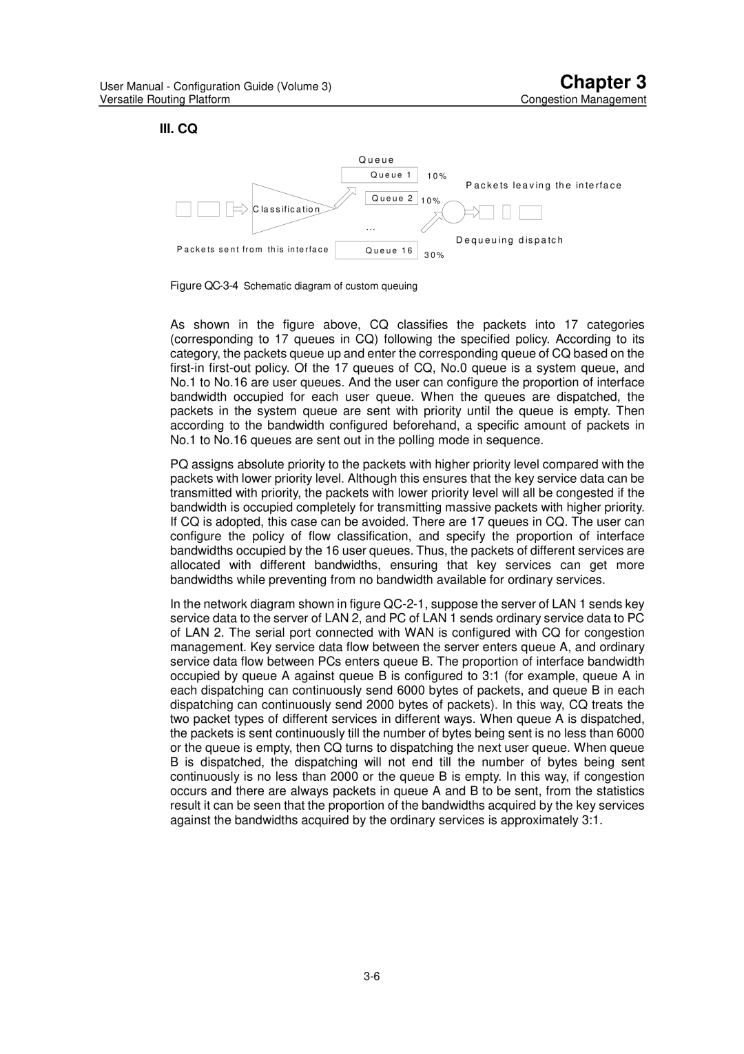
III. CQ Custom Queuing
IV. WFQ Weighted Fair Queuing
Fifo Queuing
II. PQ Priority Queuing
Selecting Congestion Management Policy
No. Advantages Disadvantages Queue
Working Principle of Congestion Management Policy
Fifo
III. CQ
Configuration of Congestion Management
Configuring PQ
PQ Configuration task list
II. Configuring priority queue
Normal low
Priority-list list-number interface type number high medium
IV. Maintaining and monitoring the priority queue
Table QC-3-7Configuration of queue length of priority queue
Interface adopts Fifo queuing by default
III. Applying priority queue to the interface
Configuring CQ
CQ configuration task list
II. Configuring the custom queue
No custom-list list-number interface type number
Operation Command Configure the default custom queue
No custom-list list-number queue queue-number byte-count
III. Applying custom queue to the interface
No custom-list list-number queue queue-number limit
Custom-list list-number queue queue-number byte-count
III. Maintenance and monitoring of the weighted fair queue
Configuring WFQ
WFQ configuration task list
II. Configuring the weighted fair queue
Configuration Example of Congestion Management
PQ Configuration Example
CQ Configuration Example
Figre QC-3-6Networking diagram of CQ Configuration
Versatile Routing Platform
Troubleshooting of Congestion Management
DDR Configuration DC
Configuring Synchronous/Asynchronous Serial Port Using DDR
DDR Configuration
DDR in Which the Router Calls Back PC
Configuration of Modem Management
DDR Configuration
Brief Introduction to Dial Configuration
Introduction to DDR Technology
Figure DC-1-1DDR configuration preparation flow
Preparing DDR Configuration
II. Configure an interface to send calls
Configuring DDR
Configuring Legacy DDR
Configuration tasks of Legacy DDR include
Dialer string dial-string isdn-address
Dialer rotary-group number
Figure DC-1-2Schematic diagram of Dialer Rotary Group
III. Configure an interface to receive calls
Versatile Routing Platform DDR Configuration
IV. Configure an interface to send and receive calls
Set the attribute parameters of Legacy DDR
Table DC-1-13Set the idle time of busy interface
Permit deny
Table DC-1-16Set access control of the dial interface
Access-list access-list-numberdeny permit
Access-list access-list-number deny permit
Configuring Dialer Profile
Default interval is 300 seconds
Introduction to Dialer Profile
II. Configuration task list of Dialer Profile
III. Configure a logic dial interface
IV. Set the attribute parameters of a dial interface
II. Terms and abbreviations
Configuring Callback
Bind physical interfaces for a dialer pool
Significance of callback
Interface dialer
IV. Configure Isdn calling line identification callback
Dialer caller remote-number callback
Or dialer caller remote-number
User name callback-dialstring telephone-number
Configure PPP callback
Chapter
Table DC-1-28Client end using Legacy DDR to configure PPP
Configure Isdn dedicated line
Configuring DDR Special Functions
II. Configure autodial
III. Configure cyclic use of dialer map
Autodial interval is 300 seconds by default
Monitoring and Maintenance of DDR
Table DC-1-34Configure cyclic use of dialer map
Name Meaning
DDR Typical Configuration Example
Legacy DDR
Network requirements
Chapter
Dialer Profile
Chapter
Networking diagram
II. Configuration procedure
Point-to-Point DDR
Chapter
Chapter
8810063
Point-to-Multipoint DDR
Chapter
Chapter
Multipoint-to-Multipoint DDR
8810052
8810148
III. Configuration procedure
Chapter
Chapter
Chapter
Chapter
DDR Bearing IPX
Chapter
Chapter
Chapter
DDR Bearing IP and IPX at the Same Time
Chapter
Chapter
Chapter
661012
Flow Control of Dialer Profile MP over Dialer Profile-Case
RouterA RouterB BRI0
2.2
Chapter
Channels for Dial-up and Connection to the Remote End Case
Figure DC-1-11Networking diagram of DDR Case
Chapter
Two Serial Ports for Dial-up and Remote Dial Connection Case
One Serial Port for Dial-up and Remote Dial Connection Case
Chapter
DDR for Access Service
Chapter
Chapter
Chapter
Chapter
DDR for Inter-Router Callback
Chapter
DDR in Which the Router Calls Back PC
III. Configuration procedure
DDR for Autodial
DDR Using Dialer Map Cyclically
Solution 1 Logical interface as backup interface
DDR Using Dialer Map as Backup
Chapter
Precautions for DDR Configuration
Configuring Dialer-group
Configuring Synchronous/Asynchronous Serial Port Using DDR
Configuring Network Layer Address
Apply PAP authentication
Configuring PPP In Dialer Profile Configuration Mode
Chapter
II. Apply Chap authentication
Chapter
Configuring PPP In Legacy DDR Configuration Mode
Chapter
II. Apply Chap authentication
Chapter
Whether modem is normal
Troubleshooting DDR
Configure Dialer-list
DDR Fault Diagnosis
III. Check whether dialer-group is configured
IV. Check whether dialer-list is configured correctly
Chapter
DDR Fault Elimination
Troubleshooting with DDR Debugging Information
How to acquire DDR debugging information
Information displayed at the calling end
Information displayed at the call receiving end
DDR link negotiation Down on interface
Function
Configuration of Modem Management
Modem Management Functions Provided by VRP1.4
Modem Script
Key words Description
Timeout seconds
Configuring Modem Script
Configuring Modem Management
Modem Management Configuration Task List
Configuring Modem Call-In and Call-Out Authorities
Configuring Modem Answer Mode
Executing Modem Script Manually
Specifying the Event to Trigger Modem Script
Managing Modem with Modem Script
Typical Configuration of Modem Management
Networking requirements
Configuration requirements
Router Initialization with Initialization Script
Direct Dial with Script
Interactively Connect Cisco Router Through Modem
VoIP Configuration VC
IP Fax Configuration
VoIP Configuration
E1 Voice Configuration
GK Client Configuration
Iphc Configuration
Versatile Routing Platform Table of Contents
VoIP Overview
VoIP Configuration
VoIP Principle
Basic composition
II. H.323 protocol stack
III. a typical telephone call processing by VoIP
IP Voice Implementation over VRP
Switch Router Capacity channel
IP Voice Feature over VRP
Chapter
Configuring Dial-peer
VoIP Configuration Task List
II. VoIP dial-peer configuration
Pots dial-peer configuration
Ip precedence priority-number
Configuring Dial Terminator
By default, we do not configure the abbreviated dialing
Configuring Abbreviated Dialing
Configuring Voice Port
By default, we do not configure the dial terminator
Table VC-1-6Configuring voice-port
Configuring Global Number Match Policy
Configuring the Recovery Method of Voice Board
By default, please use the shortest number match policy
By default, Watchdog is enabled
VoIP Monitoring and Maintenance
KHT
Rcvccactivecall
Channel = Status = Chtransframe
Configuring Router FXS Port for Interconnection
Typical VoIP Configuration Examples
III. Configuration procedures
Shanghai
Chapter
Figure VC-1-7RouterShenzhen FXO works in the Plar mode
LAN
III. Configuration description
VoIP Troubleshooting
Overview to IP Fax
IP Fax Configuration
Configuring IP Fax
Task List of IP Fax Configuration
Checking If Configuring Fax to Use ECM Mode
Configuring Fax Rate
Gateway does not use ECM mode by default
Mode is local-train mode local by default
Configuring Fax Train Mode
Configuring Fax Local-train Threshold Value
By default, the fax rate will be determined by voice mode
Fax protocol t38 hs-redundancy number
Configuring Gateway Carrier Transmit Energy Level
Fax protocol t38 ls-redundancy number
No fax protocol t38 ls-redundancy
Monitoring and Maintenance of IP Fax
By default, T.38 protocol is used
By default, rtp protocol is used
Versatile Routing Platform IP Fax Configuration
Typical Configuration of IP Fax
Chapter
Usage of cE1/PRI Interface
E1 Voice Configuration
Overview of E1 Voice Configuration
Function of E1 Voice
III. Support single stage dialing and two-stage dialing
Features of E1 Voice
Signaling modes supported
II. Protocols and standards supported
IV. Integrated transmission of voice and data
E1 Voice Configuration
Configuration Task List of E1 Voice
Configuring Pots dial-peer
No incoming called-number
Configuring VoIP dial-peer
Table VC-3-1Configuration Commands of Pots dial-peer
Incoming called-number number
Table VC-3-2Configuration Commands of VoIP dial-peer
Configuring the Basic Parameters of E1 Interface
Table VC-3-3Configuration Commands of E1 Interface
Configuring Voice Port E1 Interface
Configuring E1 Voice R2 Signaling
Configuring DS0 group
Table VC-3-4Configuration Commands of E1 Voice Port
By default, the system has not created any DS0 group
II. Configuring Related Parameters of R2 Signaling
Table VC-3-6Configuration Commands of R2 Signaling
Interface serial serial-no
Configuring the Basic Parameters of Isdn PRI Interface
Pri-group timeslots timeslots-list
No pri-group
Monitoring and Maintenance of E1 Voice
Configuring Voice Port Isdn PRI Interface
Maintaining the MFC Channel and Circuit of the Specified TS
II. show Command Related to E1 Voice
Quidway# show voice-port
R2 signalling call statistics
III. debug Commands Related to E1 Voice
Typical Configuration Examples of E1 Voice
Table VC-3-11debug Commands of E1 Voice
Router Connected to PBX through E1 Voice Port
Versatile Routing Platform
Router Connected to PBX in Isdn PRI Mode
Two-stage Dialing Configuration
II. Netwoking diagram
Transmission of Data and Voice Simultaneously
Parameter configuration of Beijing-side router
Fault Diagnosis and Troubleshooting of E1 Voice
Configuring One Interface as H.323 Gateway Interface
GK Client Configuration
Configuration of GK Client
Configuration Task List of GK Client
Activating or Deactivate GK Client Function
Configuring Gateway Alias
Configure the GK Server Name and Address
By default, GK Client function is deactivated
Configuring Tech-Prefix
Configuring GK Interworking Mode
By default, there is not any tech-prefix
Typical Configuration Examples of GK Client
Be default, the GK interworking mode is cisco mode
Versatile Routing Platform GK Client Configuration
Chapter
Fault Diagnosis and Troubleshooting of GK Client
Overview of Iphc
Iphc Configuration
No ip rtp compression-connections
Iphc Configuration
Configuration Task List of Iphc
Enable/disable RTP header compression
No ip tcp header-compression
Configure the Cisco-compatible RTP header compression
Configure the deleting of udpchk field from UDP header
By default, the udpchk field in UDP packet field is set to
Table VC-5-6Monitoring and Maintenance of Iphc
Monitoring and Maintenance of Iphc
Excellent Good Fair Poor
How Are We Doing
Mistake Suggested Correction Line No