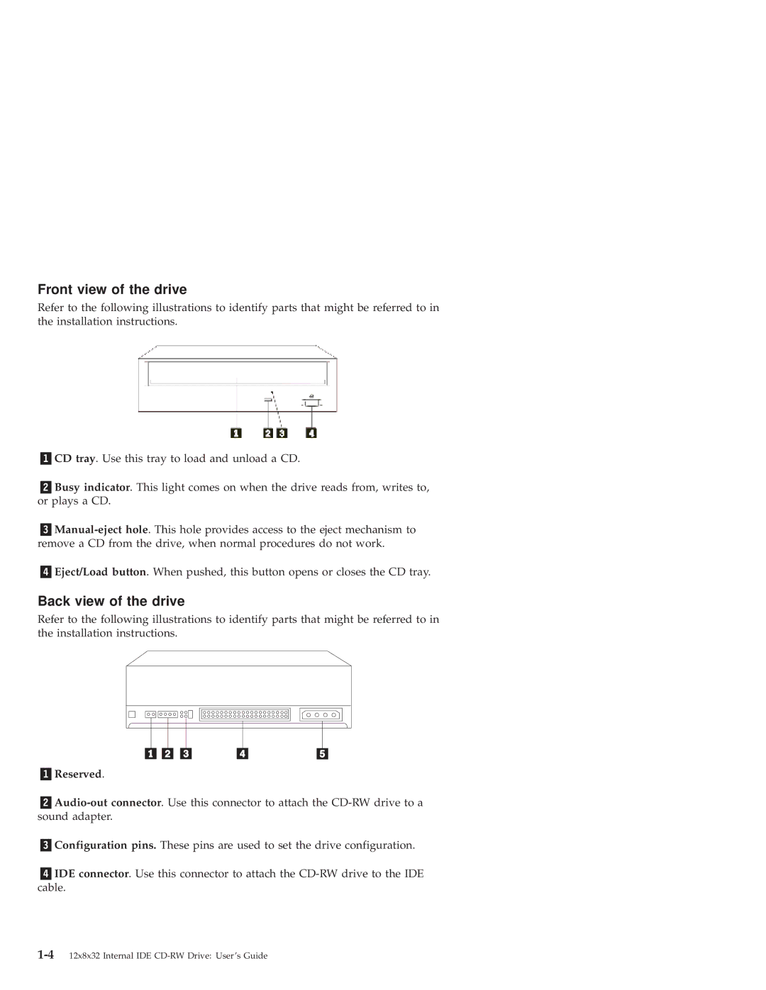
Front view of the drive
Refer to the following illustrations to identify parts that might be referred to in the installation instructions.
CD tray. Use this tray to load and unload a CD.
Busy indicator. This light comes on when the drive reads from, writes to, or plays a CD.
Eject/Load button. When pushed, this button opens or closes the CD tray.
Back view of the drive
Refer to the following illustrations to identify parts that might be referred to in the installation instructions.
Reserved.
Configuration pins. These pins are used to set the drive configuration.
IDE connector. Use this connector to attach the