Attention: Never remove the bridge card while the expansion unit is turned on. Refer to “Turning the expansion unit on and off” on page 3.
ESM and power supply bays
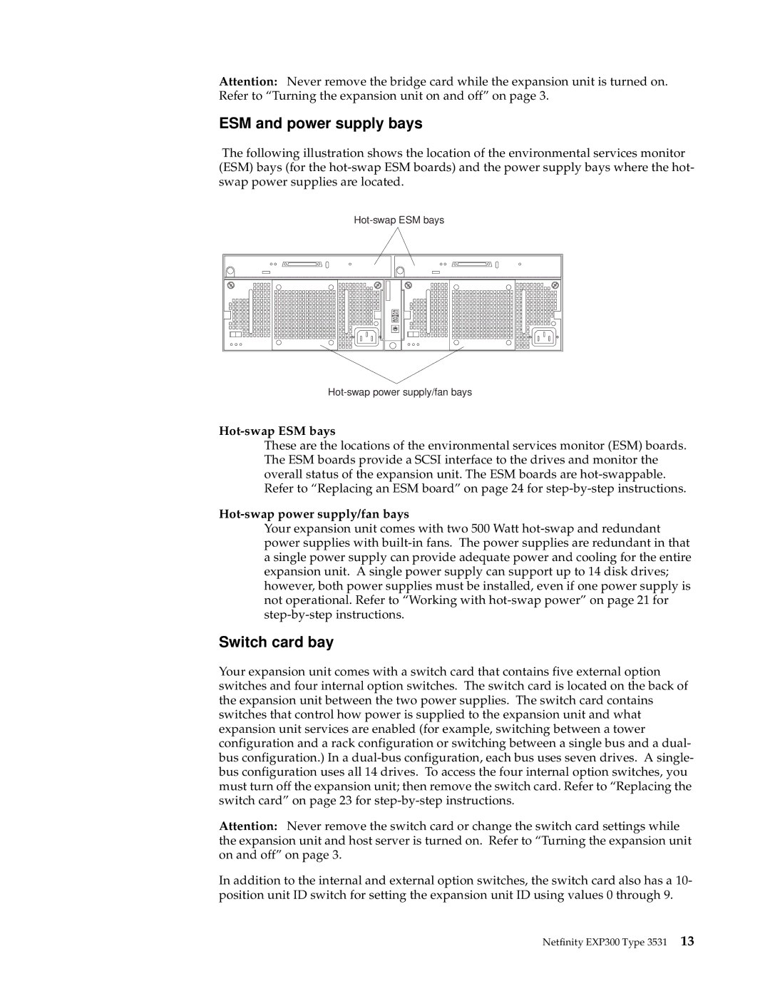
The following illustration shows the location of the environmental services monitor (ESM) bays (for the
0 1
2
7
65
Hot-swap ESM bays
These are the locations of the environmental services monitor (ESM) boards. The ESM boards provide a SCSI interface to the drives and monitor the overall status of the expansion unit. The ESM boards are
Hot-swap power supply/fan bays
Your expansion unit comes with two 500 Watt
Switch card bay
Your expansion unit comes with a switch card that contains five external option switches and four internal option switches. The switch card is located on the back of the expansion unit between the two power supplies. The switch card contains switches that control how power is supplied to the expansion unit and what expansion unit services are enabled (for example, switching between a tower configuration and a rack configuration or switching between a single bus and a dual- bus configuration.) In a
Attention: Never remove the switch card or change the switch card settings while the expansion unit and host server is turned on. Refer to “Turning the expansion unit on and off” on page 3.
In addition to the internal and external option switches, the switch card also has a 10- position unit ID switch for setting the expansion unit ID using values 0 through 9.
Netfinity EXP300 Type 3531 13