AC power connector
The power cord for the power supply connects here.
Power-supply/Fan CRU
The two
Attention: The EXP300 comes with two
The fan that is visible from the rear of the power supply is an auxiliary fan that is normally off. This fan turns on only when the main fan within the power supply fails.
Power on/off switch
Use this switch to turn the power supply on and off.
Fault LED (amber)
When completely lit, this amber fault LED indicates a power supply failure or that a redundant power supply is not on. This LED also flashes when the
DC power LED (green)
This green LED is lit when the expansion unit is turned on and is supplying both 5 V and 12 V dc power.
AC power LED (green)
This green LED is lit when the expansion unit is receiving ac power.
Handles The two handles are used for installing and removing the power supply.
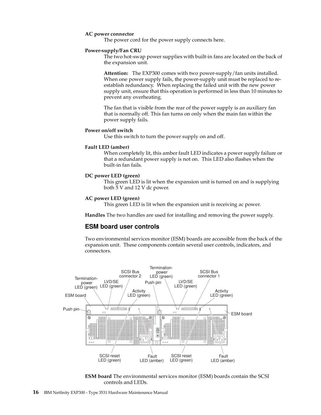
ESM board user controls
Two environmental services monitor (ESM) boards are accessible from the back of the expansion unit. These components contain several user controls, indicators, and connectors.
| SCSI Bus | Termination- | SCSI Bus | |
| power | |||
Termination- | connector 2 | LED (green) | connector 1 | |
LVD/SE | Push pin | LVD/SE | ||
power | ||||
LED (green) | LED (green) |
| LED (green) | |
| Activity | Activity | ||
ESM board | LED (green) | LED (green) | ||
Push pin![]()
ESM board
7
6
0 1
2
5
SCSI reset | Fault | SCSI reset | Fault |
LED (green) | LED (amber) | LED (green) | LED (amber) |
ESM board The environmental services monitor (ESM) boards contain the SCSI controls and LEDs.
16IBM Netfinity EXP300 - Type 3531 Hardware Maintenance Manual