For more information on option switch settings, see “Setting the interface options and ID settings” on page 10.
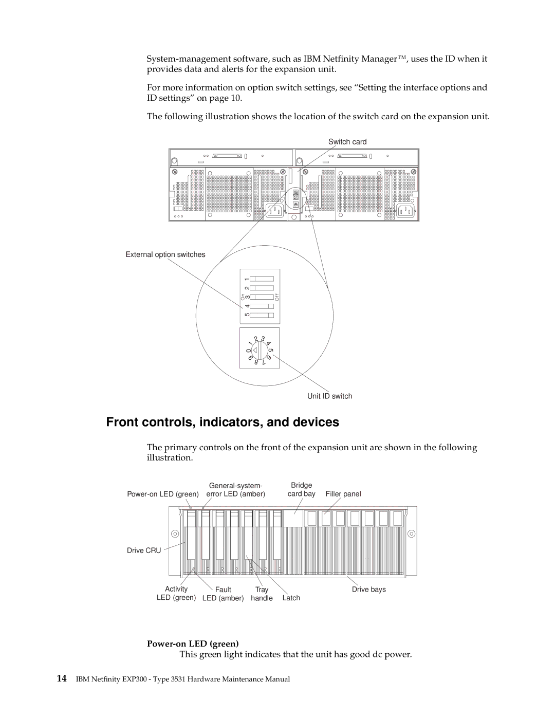
The following illustration shows the location of the switch card on the expansion unit.
Switch card
0
8
7
65
1
2 3
External option switches
5 4 3 2 1
2 1
0
9 8
3 4
5 6 7
Unit ID switch
Front controls, indicators, and devices
The primary controls on the front of the expansion unit are shown in the following illustration.
|
|
|
|
|
|
| Bridge | ||||||||||||||||||
|
| card bay Filler panel | |||||||||||||||||||||||
|
|
|
|
|
|
|
|
|
|
|
|
|
|
|
|
|
|
|
|
|
|
|
|
|
|
|
|
|
|
|
|
|
|
|
|
|
|
|
|
|
|
|
|
|
|
|
|
|
|
|
|
|
|
|
|
|
|
|
|
|
|
|
|
|
|
|
|
|
|
|
|
|
|
|
|
|
|
Drive CRU
Activity | Fault | Tray | Drive bays |
LED (green) | LED (amber) | handle | Latch |
Power-on LED (green)
This green light indicates that the unit has good dc power.
14IBM Netfinity EXP300 - Type 3531 Hardware Maintenance Manual