Pin Assignments |
|
|
|
|
|
|
|
|
|
|
| |||
X.21 | Connector | Information |
|
|
|
|
|
|
|
|
| |||
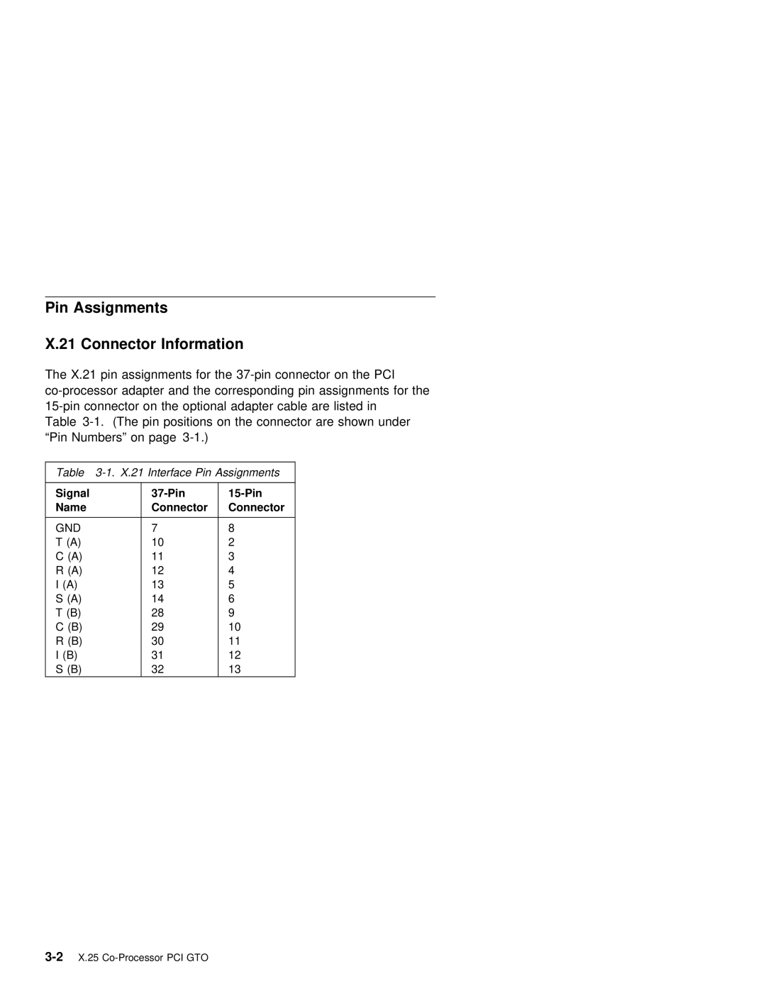
The | X.21 pin | assignments for | the | |||||||||||
and | the |
| corresponding pin | assignments | for the | |||||||||
adapter cable | are | listed | in | |||||||||||
Table | pin | positions | on |
| the connector | are | shown under | |||||||
“Pin | Numbers” | on | page |
|
|
|
|
|
|
| ||||
|
|
|
|
|
|
|
|
|
|
|
| |||
Table | Interface | Pin |
| Assignments |
|
|
| |||||||
|
|
|
|
|
|
|
|
|
|
|
|
| ||
Signal |
|
|
|
|
|
|
|
|
|
| ||||
Name |
|
|
| Connector |
| Connector |
|
|
|
|
|
| ||
|
|
|
|
|
|
|
|
|
|
|
|
|
| |
GND |
|
| 7 |
|
| 8 |
|
|
|
|
|
|
| |
T | (A) |
|
| 10 |
|
| 2 |
|
|
|
|
|
|
|
C | (A) |
|
| 11 |
|
| 3 |
|
|
|
|
|
|
|
R | (A) |
|
| 12 |
|
| 4 |
|
|
|
|
|
|
|
I | (A) |
| 13 |
|
| 5 |
|
|
|
|
|
|
| |
S | (A) |
|
| 14 |
|
| 6 |
|
|
|
|
|
|
|
T | (B) |
|
| 28 |
|
| 9 |
|
|
|
|
|
|
|
C | (B) |
|
| 29 |
|
| 10 |
|
|
|
|
|
|
|
R | (B) |
| 30 |
|
| 11 |
|
|
|
|
|
|
| |
I | (B) |
| 31 |
|
| 12 |
|
|
|
|
|
|
| |
S | (B) |
|
| 32 |
|
| 13 |
|
|
|
|
|
|
|