Technical Product Specification
July
Technical Product Specification
Contents
Interrupts and Error Reporting 10.1
Mean Time Between Failure Mtbf Specifications 1.1
104
138
Tables
OOS LED DS9
111
Revision History
Date Revision Description
Introduction1
Document Organization
Glossary
Acpi
Mtbf
Features Overview
Application
Functional Description
Intel NetStructure MPCBL0001 SBC Block Diagram
ECC
Low Voltage Intel Xeon Processor CPU-0 U35, CPU-1 U36
Chipset
Intel E7501 Memory Controller Hub U22
Intel 82801CA I/O Controller Hub 3 U7
PCI Bus Master IDE Interface J24
P64H2 Interfaces
Memory J8, J9, J10, J11
Intel 82870P2 64-bit PCI/PCI-X Controller Hub 2 U14, U24
P64H2 Device Interface
4 I/O
Memory Ordering Rule for the MCH
Super I/O U28
Timer0 Capabilities
Real-Time Clock
Gigabit Ethernet U13
Fibre Channel* U23 Optional
PMC Connector J25, J26, J27
Firmware Hub U30, U33
FWH 0 Main Bios
FWH 1 Backup/Recovery Bios
Flash ROM Backup Mechanism
Onboard Power Supplies
Ipmb Standby Power
Hardware Management Block Diagram
Hardware Management Overview
Ipmc
Sensor Data Record SDR
Hardware Sensors Sheet 1
PCI Serr Ipmc
CPU 0 Ierr Ipmc
Hardware Sensors Sheet 2
BAT
CPU 1 Ierr Ipmc
System Event Log SEL
Hardware Sensors Sheet 3
IPMB-0
Event Remarks Type Type Code
SEL Events Supported by the MPCBL0001 SBC Sheet 1
Sensor Sensor-Specific
Ierr
SEL Events Supported by the MPCBL0001 SBC Sheet 2
Sensor
Event Remarks Type
SEL Events Supported by the MPCBL0001 SBC Sheet 3
PCI Perr
PCI Serr
Temperature and Voltage Sensors
SEL Events Supported by the MPCBL0001 SBC Sheet 4
Offset Event Remarks Type Type Code Data 1, Bit
Normal
Sensor Thresholds for Ipmc Firmware
Sensor Name
Number
Sensor Normal
+5VSB
Sensor Thresholds for Ipmc Firmware 1.7 and Above
Sensor Thresholds for Ipmc Firmware 1.14 and Above
Dimm Memory Events
System Firmware Progress Post Error
Processor Events
Critical Interrupts
PCI Mapping for Hardware Component Subsystem
Bus Device Function Hardware Component Subsystem
0XFF
FRU Hot Swap
System Acpi Power State
Ipmb Link Sensor
CPU Failure Detection
CPU Identification
Port 80h Post Codes
CPU Failure Behavior
Health LED
Variable Size byte Data Type
Field Replaceable Unit FRU Information
PMC Data
Variable Size Data Type
Keying
Ipmc Firmware Code
Link Descriptors for E-Keying
Ipmc Firmware Upgrade Procedure
Ipmc Firmware Upgrade Using KCS Interface
Ipmc Firmware Code Process
Ipmc Firmware Upgrade via the Ipmb Interface Rmcp
Upgrade via Remote Management Node
Reset Bios Flash Type
OEM Ipmi Commands
Reset Bios Flash Type
Updating MPCBL0001 Firmware
Set Fibre Channel Port Selection
Set Fibre Channel Port Selection
Get Fibre Channel Port Selection
Get Fibre Channel Port Selection
Get HW Fibre Channel Port Selection
Set Control State
Controls Identifier Table
Get Control State
Get Port80 Data
Hot-Swap Process
Hot-Swap Process
Hot-Swap LED DS11
Hot-Swap LED DS10
Ejector Mechanism
LED Status Meaning
Interrupt Assignments Sheet 1
Interrupts and Error Reporting
Device Interrupts
Legacy Interrupt IRQ assigned
Interrupt Assignments Sheet 2
Error Reporting
Power States and Targeted System Power
Reset Types
System States and Power States
Acpi
Reset Logic
Hard Reset Request
Soft Reset Request
Warm Boot
Reset Request
Reset Request Signal Activated Type
Reset Actions
Cold Boot
Power Good
Reset Actions System Function Memory Status
Hardware Management Overview
Reset Chain
Watchdog Timers WDTs
WDT #1
WDT #2
WDT #3
Health LED
OOS Out Of Service LED
LED Status
Hot-Swap LED
IDE Drive Activity LED
IDE Drive Activity LED
User Programmable LEDs
User Programmable LEDs
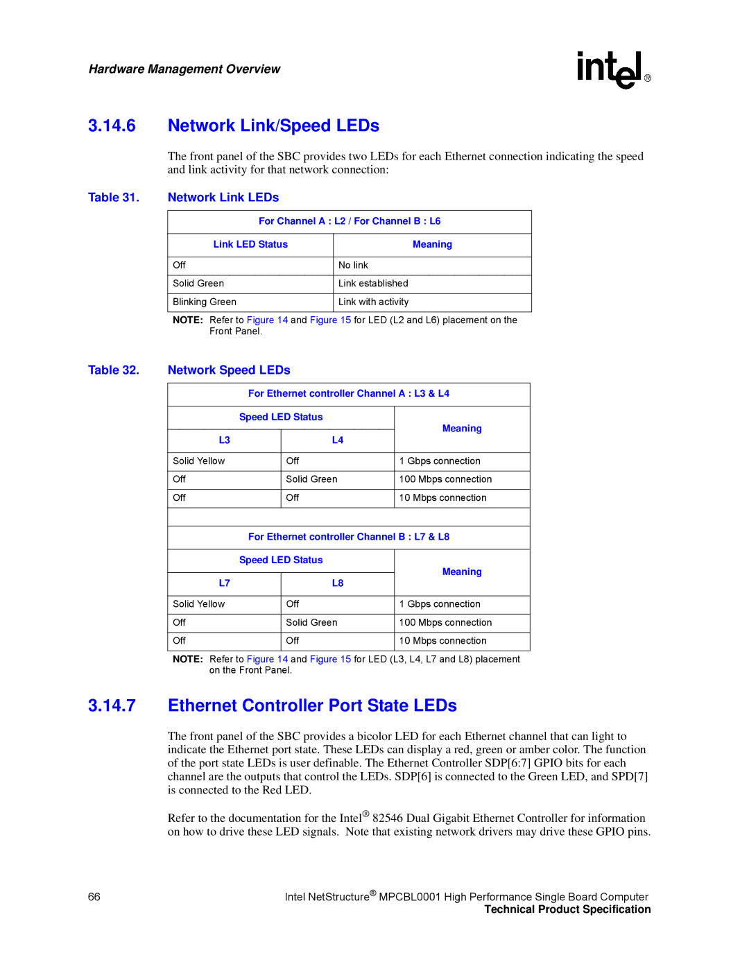
Network Link LEDs
Network Link/Speed LEDs
Ethernet Controller Port State LEDs
Network Speed LEDs
Fibre Channel Port State LEDs
CMM Commands for FRU Control Options
FRU Payload Control
Ethernet Controller Port State LED
Cold Reset
Warm Reset
Graceful Reboot
Diagnostic Interrupt
Returned Values from the Get Message Command
Byte Data Value Comments
Connectors4
MPCBL0001 SBC Connector Locations
MPCBL0001NXX SBC Front Panel
MPCBL0001FXX SBC Front Panel
Front Panel Description Details Connectors
Connector Assignments
Backplane Description Details Connectors
LED Descriptions
Power Distribution Connector Zone 1 P10 Pin Assignments
Backplane Connectors
Power Distribution Connector Zone
Pin # Signal Name Description
Data Transport Connector Zone
Data Transport Connector Zone 2 P23 Pin Assignments
Alignment Blocks
Serial Port Connector J17
Front Panel Connectors
USB Connector J12
USB Connector J12 Pin Assignments
Serial Port Connector J17 Pin Assignments
Connector Pin Serial Port Signal Number
DB9 to RJ-45 Pin Translation
Fibre Channel SFP Optical Transceiver Module
Fibre Channel SFP Copper Transceiver Module AMP, J34, J35
PMC Connectors J25, J26, J27
Fibre Channel SFP Pin Assignments
PMC Connector Pin Assignments 32 Bit
J25 Bit PCI Pin Signal
J26 Bit PCI Pin Signal
PMC Connector Pin Assignments 64 Bit
J27 Bit PCI Pin Signal
PAR64
IDE Connector Pin Assignments
On-board Connectors
IDE Connector J24
Pin # Signal Name
Configuration Data Register MCH Configaddress
Configuration Registers
Configuration Address Register MCH Configaddress
Configuration Address Register Bit Assignments
Address Cross-References
Configuration Data Register Bit Assignments
I/O Address Assignments
Device Document Title/Number Section/Page/Table
Memory Map
Memory Map
Memory Device Address Size
Bit Ad dress W/R SMBus Description
Ipmc Addresses
SMBus Addresses
SEL Eeprom
Specifications6
Mechanical Specifications
Board Outline
Intel NetStructure MPCBL0001 Component Layout
MCH
Backing Plate
Component Height
Specifications
MPCBL0001 SBC Front Panel Dimensions FC SKU Screws and LEDs
Specifications
Specifications
Mean Time Between Failure Mtbf Specifications
Environmental Specifications
Reliability Specifications
Environmental Specifications
Environmental Assumptions
Power Consumption
Total Measured Power
General Assumptions
Board Layer Specifications
Weight
Cooling Requirements
Copying and Saving Cmos Settings
Bios Features
Bios Flash Memory Organization
Introduction
Redundant Bios Functionality
System Management Bios Smbios
Bios Updates
Legacy USB Support
CD-ROM and Network Boot
Recovering Bios Data
Boot Options
Booting without Attached Devices
Fast Booting Systems
Bios Security Features
Quick Boot
Remote Access Configuration
Supervisor and User Password Functions
Function Key Escape Code Equivalents
Bios Setup Program Function Keys
Bios Setup
Bios Setup Program Menu Bar
Main Menu
Advanced Menu
Feature Options Description
Bios ID
Main Menu
CPU Configuration Submenu
Advanced Menu
Picmg
IDE Configuration Submenu
CPU Configuration Submenu
IDE Configuration Submenu Sheet 1
IDE Configuration Submenu Sheet 2
Primary IDE Master/Slave Submenu
Primary IDE Master/Slave Submenu
Floppy Configuration Submenu
Floppy Configuration Submenu
SuperIO Configuration Submenu
SuperIO Configuration Submenu
Acpi Configuration Submenu
Acpi Configuration Submenu
Advanced Acpi Configuration Submenu
Advanced Acpi Configuration Submenu
System Management Configuration Submenu
System Management Configuration Submenu
Event Logging Configuration Submenu
Event Logging Configuration Submenu
Fibre Channel Routing Picmg Configuration Submenu
Fibre Channel Routing Picmg Submenu
Remote Access Configuration Submenu
Remote Access Configuration Submenu
VT-UTF8
USB Configuration Submenu
USB Configuration Submenu
USB Mass Storage Device Configuration
PCI Configuration
USB Mass Storage Device Configuration
Cdrom
PCI Configuration Submenu
Boot Menu
Boot Settings Configuration Submenu
Boot Menu
Boot Device Priority Submenu
Boot Settings Configuration Submenu
Hard Disk Drive Submenu
OS Load Timeout Timer
Boot Device Priority Submenu
Hard Disk Drive Priority Submenu
Exit Menu
OS Load Timeout Timer Submenu
Security Menu
Security Menu
Exit Menu
Bios Error Messages
Error Messages
Bios Error Messages
Explanation of Error Message
Checkpoint Description
Bootblock Initialization Code Checkpoints
Port 80h Post Codes
EC-EE
Post Code Checkpoints Sheet 1
Post Code Checkpoints Sheet 2
Acpi Runtime Checkpoints
Bios Beep Codes
DIM Code Checkpoints
Number of Beeps Description
Procedures to Copy and Save Bios Including Cmos Settings
Bios Configuration
Bios Image Updates
Copying BIOS.bin from the SBC
Saving BIOS.bin to the SBC
Error Messages
Error Message
Jumper/Connector Locations
Jumpers
J37 Jumper assignments
J18 Pin Assignments
J16 Jumper Assignments
Lattice* Compatible Jtag Header PS/2 Keyboard/Mouse Header
Digital Ground to Chassis Ground Connectivity
J40 Jumper Assignments
Supervision
Maintenance11
Diagnostics
In-Target Probe ITP
Power vs. Flow Rate
Thermals12
Code Name Brand Name Package Type
Component Technology
Main Components
ICH3
Warranty Information
Returning a Defective Product RMA
For the Americas
For Europe, Middle East, and Africa Emea
For Asia and Pacific Apac
Warranty Information
Customer Support
Technical Support and Return for Service Assistance
Customer Support
Sales Assistance
Certifications16
Bsmi
North America FCC Class a
Safety Instructions English and French-translated
Agency Information-Class a
English
Taiwan Class a Warning Statement
French
Japan Vcci Class a Korean Class a Australia, New Zealand
Agency Information-Class B
North America FCC Class B
Japan Vcci Class B
Korean Class B Australia, New Zealand
Safety Warnings
Not the Main Disconnect
Mesures de Sécurité
Safety Warnings
Sicherheitshinweise
Safety Warnings
Norme di Sicurezza
Safety Warnings
Instrucciones de Seguridad
Safety Warnings
Chinese Safety Warning
Reference Documents
Reference Documents
Command NetFn
List of Supported Commands Ipmi
Ipmi 1.5 Supported Commands Sheet 1
Picmg
List of Supported Commands Ipmi v1.5 and Picmg
Ipmi 1.5 Supported Commands Sheet 2
SDR Device Commands NetFn
Ipmi 1.5 Supported Commands Sheet 3
Picmg 3.0 Ipmi Supported Commands
SEL Device Commands NetFn
List of Supported Commands Ipmi v1.5 and Picmg