MNEMONIC | FUNCTION | TYPE |
S1 - S4 | Set/Print I/O Point Type/Active State | I/O Instruction |
DESCRIPTION
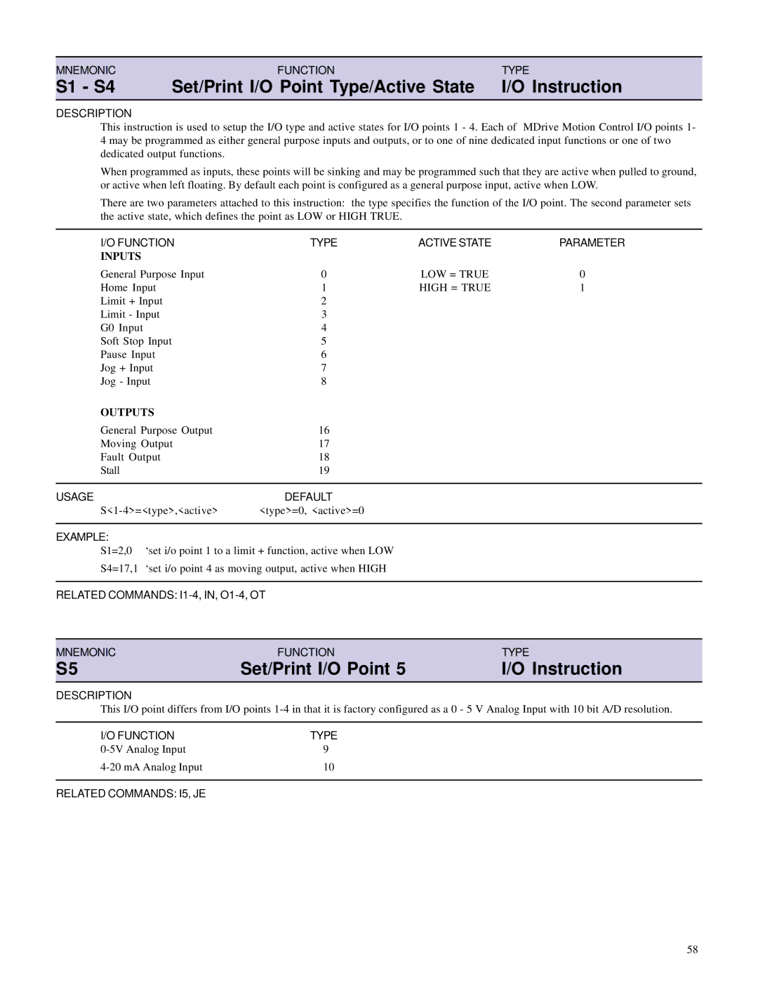
This instruction is used to setup the I/O type and active states for I/O points 1 - 4. Each of MDrive Motion Control I/O points 1- 4 may be programmed as either general purpose inputs and outputs, or to one of nine dedicated input functions or one of two dedicated output functions.
When programmed as inputs, these points will be sinking and may be programmed such that they are active when pulled to ground, or active when left floating. By default each point is configured as a general purpose input, active when LOW.
There are two parameters attached to this instruction: the type specifies the function of the I/O point. The second parameter sets the active state, which defines the point as LOW or HIGH TRUE.
I/O FUNCTION | TYPE | ACTIVE STATE | PARAMETER |
INPUTS |
|
|
|
General Purpose Input | 0 | LOW = TRUE | 0 |
Home Input | 1 | HIGH = TRUE | 1 |
Limit + Input | 2 |
|
|
Limit - Input | 3 |
|
|
G0 Input | 4 |
|
|
Soft Stop Input | 5 |
|
|
Pause Input | 6 |
|
|
Jog + Input | 7 |
|
|
Jog - Input | 8 |
|
|
OUTPUTS |
|
|
|
General Purpose Output | 16 |
|
|
Moving Output | 17 |
|
|
Fault Output | 18 |
|
|
Stall | 19 |
|
|
|
|
|
|
USAGE | DEFAULT |
|
|
<type>=0, <active>=0 |
|
|
EXAMPLE:
S1=2,0 ‘set i/o point 1 to a limit + function, active when LOW
S4=17,1 ‘set i/o point 4 as moving output, active when HIGH
RELATED COMMANDS:
MNEMONIC | FUNCTION | TYPE |
S5 | Set/Print I/O Point 5 | I/O Instruction |
DESCRIPTION
This I/O point differs from I/O points
I/O FUNCTION | TYPE |
9 | |
10 |
RELATED COMMANDS: I5, JE
58
