I n t e r f a c i n g t h e D i g i t a l I / O
The MDrive Motion Control comes standard with a set of four (4) open collector +5 to +24VDC I/O point which may be programmed individually as either general purpose or dedicated inputs or outputs, or collectively as a group.
The digital I/O may be defined as either active HIGH or active LOW. When the I/O is configured as active HIGH, the level is +5 to +24 VDC and the state will be read/set as a “1”. If the level is 0 VDC then the state will be read/set as “0”. Inversely, if configured as active LOW, then the state of the I/O will be read/set as a “1” when the level is LOW, and a “0” when the level is HIGH. The active HIGH/LOW state is configured by the third parameter of the I/O Setup
The MDrive Motion Control’s I/O scheme is a powerful tool for machine and process control.
U s e s o f t h e D i g i t a l I / O
The I/O may be utilized to receive input from external devices such as sensors, switches or PLC outputs. When configured as outputs, devices such as relays, solenoids, LED’s and PLC inputs may be controlled from the MDrive Motion Control.
Each I/O point may be individually programmed to any one of 9 dedicated input functions, 3 dedicated output functions, or as general purpose inputs or outputs. The I/O may be addressed individually, or as a group. The active state of the line or group may also be set. All of these possible functions are accomplished with of the I/O Setup Variable
I n t e r f a c i n g I n p u t s
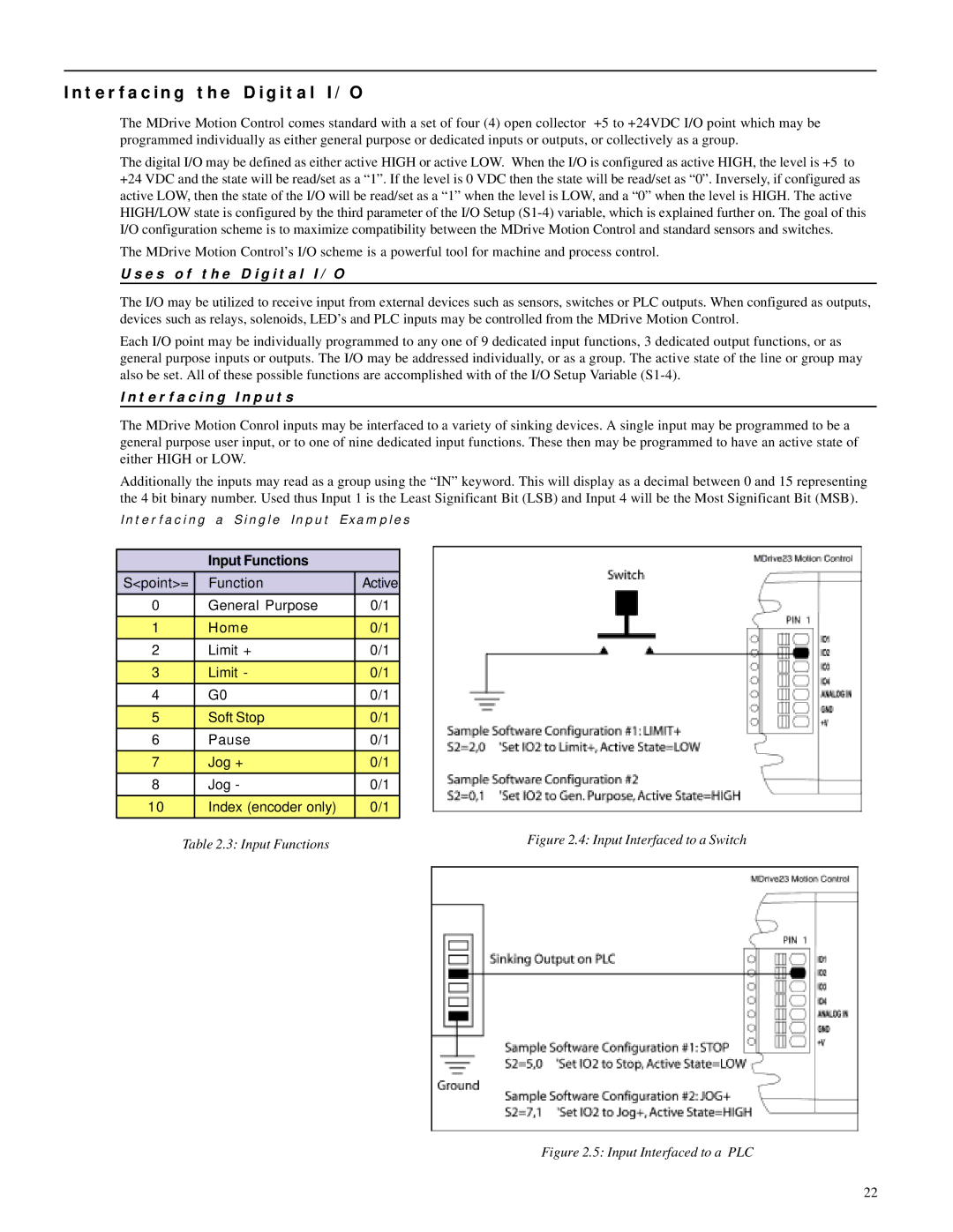
The MDrive Motion Conrol inputs may be interfaced to a variety of sinking devices. A single input may be programmed to be a general purpose user input, or to one of nine dedicated input functions. These then may be programmed to have an active state of either HIGH or LOW.
Additionally the inputs may read as a group using the “IN” keyword. This will display as a decimal between 0 and 15 representing the 4 bit binary number. Used thus Input 1 is the Least Significant Bit (LSB) and Input 4 will be the Most Significant Bit (MSB).
I n t e r f a c i n g a S i n g l e I n p u t E x a m p l e s
| Input Functions |
|
|
S<point>= | Function | Active |
|
0 | General Purpose | 0/1 |
|
1 | Home | 0/1 |
|
2 | Limit + | 0/1 |
|
3 | Limit - | 0/1 |
|
4 | G0 | 0/1 |
|
5 | Soft Stop | 0/1 |
|
6 | Pause | 0/1 |
|
7 | Jog + | 0/1 |
|
8 | Jog - | 0/1 |
|
10 | Index (encoder only) | 0/1 |
|
Table 2.3: Input Functions |
| Figure 2.4: Input Interfaced to a Switch | |
Figure 2.5: Input Interfaced to a PLC
22
