SECTION 12—ANTI-TIPPERS
| Mounting Bolts |
|
Washers | Washers | Base Frame |
|
|
Coved Washers
| Coved Washers | |
|
| |
| Washers | Washers |
|
| |
|
| Locknuts |
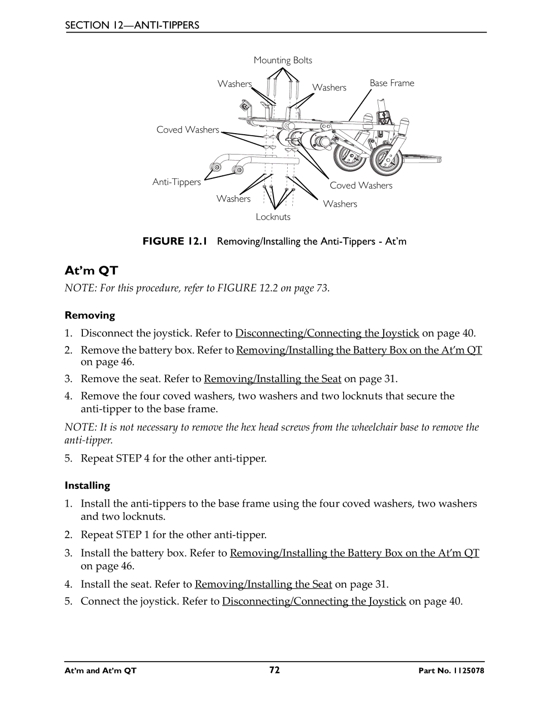
FIGURE 12.1 Removing/Installing the Anti-Tippers - At’m
At’m QT
NOTE: For this procedure, refer to FIGURE 12.2 on page 73.
Removing
1.Disconnect the joystick. Refer to Disconnecting/Connecting the Joystick on page 40.
2.Remove the battery box. Refer to Removing/Installing the Battery Box on the At’m QT on page 46.
3.Remove the seat. Refer to Removing/Installing the Seat on page 31.
4.Remove the four coved washers, two washers and two locknuts that secure the
NOTE: It is not necessary to remove the hex head screws from the wheelchair base to remove the
5. Repeat STEP 4 for the other
Installing
1.Install the
2.Repeat STEP 1 for the other
3.Install the battery box. Refer to Removing/Installing the Battery Box on the At’m QT on page 46.
4.Install the seat. Refer to Removing/Installing the Seat on page 31.
5.Connect the joystick. Refer to Disconnecting/Connecting the Joystick on page 40.
At’m and At’m QT | 72 | Part No. 1125078 |
