SECTION 8—BATTERIES
Installing
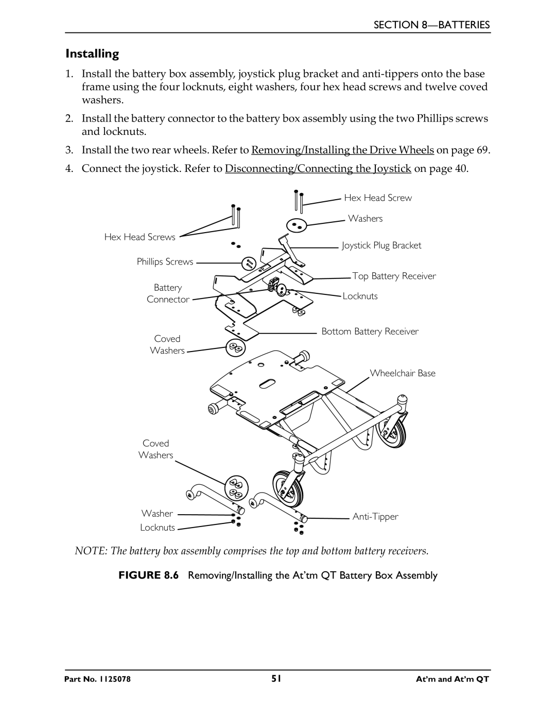
1.Install the battery box assembly, joystick plug bracket and
2.Install the battery connector to the battery box assembly using the two Phillips screws and locknuts.
3.Install the two rear wheels. Refer to Removing/Installing the Drive Wheels on page 69.
4.Connect the joystick. Refer to Disconnecting/Connecting the Joystick on page 40.
Hex Head Screw
| Washers | |
Hex Head Screws | Joystick Plug Bracket | |
| ||
Phillips Screws |
| |
| Top Battery Receiver | |
Battery | Locknuts | |
Connector | ||
| ||
Coved | Bottom Battery Receiver | |
| ||
Washers |
| |
| Wheelchair Base |
Coved
Washers
Washer ![]()
![]()
![]()
Locknuts
NOTE: The battery box assembly comprises the top and bottom battery receivers.
FIGURE 8.6 Removing/Installing the At’tm QT Battery Box Assembly
Part No. 1125078 | 51 | At’m and At’m QT |