GY-DV5001MANUEL D’INSTRUCTIONS Instrucciones Istruzioni
LWT0074-001C-H
Port Cable Length
DV signal input is possible with the GY-DV5001E
These instructions are for the GY-DV5000E and GY-DV5001E
Rating plate serial number plate is on the top frame
Main Features
AC Operation Battery Pack Operation Optional
Main Features
Connecting a Video Component with DV Connector
11-11
Precautions for Proper Use
Introduction
Head cleaner Tape guides & rollers
Routine and Periodical Maintenance
Precautions for Use of Head Cleaning Tape
Time management
Videocassette to be Used
Battery Pack to be Used
Use JVC’s videocassette tapes marked with the or Symbol
For recording and storing videotapes in the best condition
Smear and Blooming
Characteristic CCD Phenomena
Condensation
Moire or Aliasing
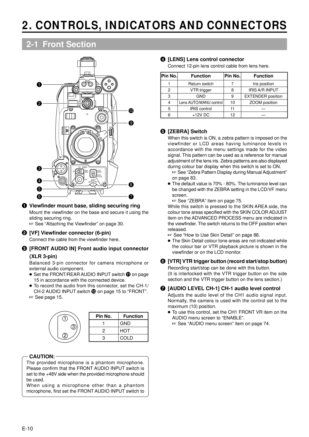
CONTROLS, Indicators and Connectors
Front Section
Lens mounting ring/Lens lock lever
Auto WHITE/ACCU Focus switch
Filter Colour temperature conversion filter control knob
White Balance
Right Side Section
VTR VTR mode indicator
Black Black stretch/black compression switch
CAM Camera mode indicator
Power Power ON/OFF switch
Right Side Section Cont’d
# Counter Counter display switch
CH-1/CH-2 Audio Input CH-1/CH-2 audio input selector switch
@ Monitor Select Audio monitor selector switch
$ TC GENE. Time code generator setting switch
C OUT Y/C output connector 4-pin
Monitor OUT Monitor output connector BNC
CH1/CH2 Line OUT CH1/CH2 line output connector RCA
Left Side Section
Top Section
Rear Section
Battery holder lock release knob
DV connector
Battery holder
Breaker Breaker button
Indications on the LCD Monitor and in the Viewfinder
Camera mode Example of display
VTR mode Example of display
Status Screens
Status Screens in the Camera Mode
Indications on the LCD Monitor and in the Viewfinder Cont’d
Status Screen in VTR Mode
Magnified Status Indications on the LCD Monitor
Ntsc Inhibit
Cleaning Tape
Head Cleaning Required
REC Inhibit
Menu Setting Screen
Auto White Balance Indication Camera mode only
Safety Zone Indication Camera mode only
TOP Menu screen Camera mode
Zoom Lens Optional
S14 x 7.3B12U
1.5-Inch Viewfinder Optional
VF-P115B
Basic System Connections and Adjustments
Basic System
Pin Hole
Attaching the Zoom Lens
Attaching the Viewfinder
Viewfinder
Attaching the Microphone Provided
Attaching the Microphone Using KA-A50U
Attaching the Microphone Optional
Tripod mounting holes
Front mount clip Safety lever Lock lever
Attaching the Tripod Base Provided
Front base mount
Flat shape type battery pack Anton-Bauer battery pack
Power Supply
Battery Pack Operation Optional
AC Operation
Battery Pack Operation Optional Cont’d
Using a Flat Shape Type Battery Pack optional
Attaching the Battery Pack
Using an Anton-Bauer Battery Pack
Detaching the Battery Pack
Recharging
Operating Time with Battery Pack
Battery Pack Continuous Operating Time at 25 ˚C
Sony
Mode Operation
Turning the Power on
Turning the Power OFF
Preparations
REC Save
Cassette Loading and Unloading
Loading the Cassette
VTR
Open knob
Unloading the Cassette
Cassette cover Eject button
Opening the LCD monitor
Adjusting the LCD monitor
Viewing the LCD Monitor
Changing the orientation and angle of the LCD monitor
Dial
Setting, Displaying and Recording the Date and Time
Setting the Date and Time
Menu
Setting, Displaying and Recording the Date and Time Cont’d
Clock Adjust menu screen Date Year/Month/Day
Displaying the Time and Date on the Screen
Recording the Date and Time Data
How to charge
Charging the Built-in Battery
AC outlet AA-P250 DC cable
Filter
Camera Settings
Screen Size 43/LETTER Mode Selection
Suitable Location
Adjust the position and angle of the viewfinder
Viewfinder Adjustment
External Monitor Adjustment
Colour video monitor
Back Focus Adjustment
Accu Focus can also be used in the above step
White Balance Adjustment
Line
Audio Input Signal Selection
MIC
Auto mode is selected in the Full Auto shooting mode
Recording Level Adjustment
Using the audio input level control on the front section
Monitor Select switch
Monitoring Audio during Recording
Shooting Operation
Basic Recording Operation
About the Quick REC Start Mode
When it is required to unload the videocassette
When the power should be turned off
Tally lamp
Screen indications during Edit Search
Searching for Recorded Scenes Edit Search
Edit Search
Searching the tape in forward direction
If the Record-Standby Mode Continues
Setting the time before the tape protection mode is Engaged
Header REC Function
Header REC menu screen contents
Description
Executing the Header REC Function
How to set the Header REC menu screen
During Header REC
Colour bar signal of the built-in signal generator
Output switch
Recording the Colour Bars
Power switch Mode switch
Playback Mode
Playback Procedure
Display of time code
Search
Fast-Forward, Rewind
Blank Search
Outputting CH-3, CH-4 Channel Audio
Setting
VTR indicator
Shutter dial Status button TOP Menu screen
Connecting a Video Component with DV Connector
Using External Components
DV connector DV cable VC-VDV204 4P-4P, VC-VDV206 4P- 6P
Date and time data
Settings
Operation Connections
Data transmitted from the playback unit is recorded
Time Code Operation
Presetting and Recording of Time Code
TC GENE. switch
Displaying Time Code
Zero-resetting the Time Code or User’s Bit Data
Time code hour, min, sec, frame
Reproducing Time Codes
Set the TC Gene switch inside the cover on the side to
TC Gene switch
Regen
11-1Menu Screen Configuration
Menu Screens
Shutter STA
11-2Setting Menu Screens
Status button
Termenu dial Cursor Menu screen
Resetting the Menu Settings to the Factory Settings
Storing Setting Values
Reading Out a Menu Settings File
11-3FILE Manage Menu Screen
11-4TOP Menu Screen
11-5CAMERA Operation Menu Screen
11-6CAMERA Process Menu Screen
11-8SKIN Color Adjust Screen
11-7ADVANCED Process Screen
11-9AUDIO Menu Screen
11-10 LCD/VF Menu Screen
11-10 LCD/VF Menu Screen Cont’d
11-11 TC/UB/CLOCK Menu Screen
Header REC Menu Screen
TIME/DATE Menu Screen
Others Menu Screen
Type
Alarm VR
Battery
Front
WHT.BAL switch
Features of the Camera Section
Setting procedure
Full-Time Auto White Balance FAW
Manual adjustment
Iris Brightness Adjustment
Automatic adjustment
Temporary auto iris adjustment
Shutter STA TER
Adjusting the Shutter Speed
Operation
Set the Shutter item on the Camera Operation menu screen
Band Video monitor
Shooting the Screen Image on a Computer Monitor
� Variable Scan V.SCAN
Basic operation
Switch Position Factory-Set Gain
Gain Sensitivity Adjustment
Gain switch
Relationship between gain, iris and shutter
Switch Setup According to Illumination and Subject
Automatic Setting Contents
Detection
How to Use Skin Detail
Setting the Color and Range of the Skin Detail Function
Area
Status
Using the Skin Detail Function
Display
Screen indications on the LCD monitor and in the Viewfinder
Alarm Indications and Actions
Others
Indication Condition Remedy
Blinking Pattern Remaining Battery/Tape
Error Code Error Details GY-DV5000 Operation Remedy
Tally lamp
Alarm Sound
Alarm Indications and Actions Cont’d
Camera to operate REC/ALARM lamp Battery lamp
Viewfinder Warning Lamps
Tape. See Precautions for Use of Head Cleaning Tape on
Troubleshooting
Symptoms Remedy
Type
Others 2/2 menu screen
Hour Meter Display
Shutter dial Status button
Accumulated drum running time
Specifications
Viewfinder VF-P115B, VF-P116 Power zoom lens
Specifications Cont’d
External Dimensions unit mm
YH16 ⋅ 7K12U, YH19 ⋅ 6.7K12U Canon
GY-DV5000/GY-DV5001 DV Camcorder