CONTROLS, INDICATORS AND CONNECTORS
CONTROLS, INDICATORS AND CONNECTORS
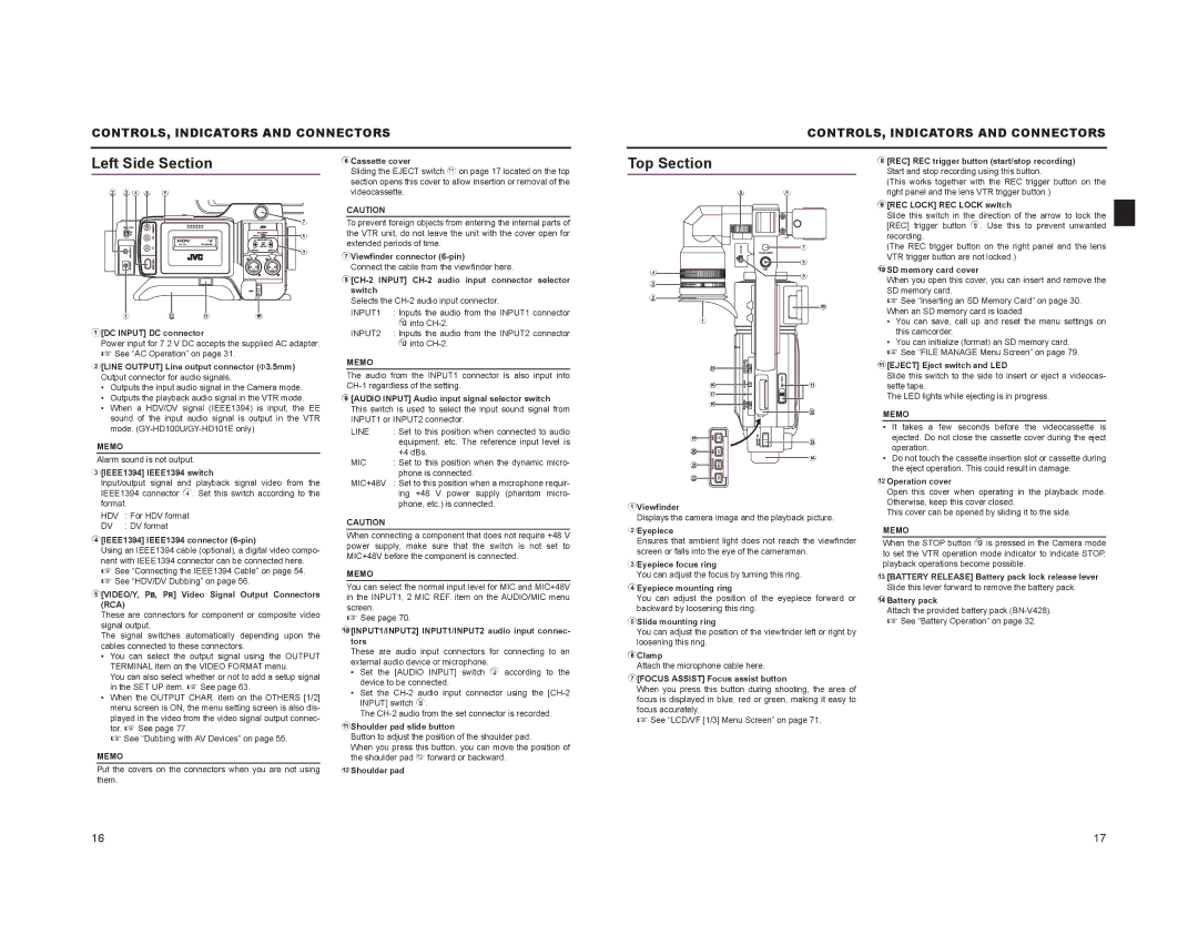
Left Side Section
6Cassette cover
Sliding the EJECT switch a on page 17 located on the top
Top Section
8[REC] REC trigger button (start/stop recording) Start and stop recording using this button.
2 3 4 5 | 6 |
7
![]() 8
8
9
1 b a 0
1[DC INPUT] DC connector
Power input for 7.2 V DC accepts the supplied AC adapter. X See “AC Operation” on page 31.
2[LINE OUTPUT] Line output connector ()3.5mm) Output connector for audio signals.
•Outputs the input audio signal in the Camera mode.
•Outputs the playback audio signal in the VTR mode.
•When a HDV/DV signal (IEEE1394) is input, the EE sound of the input audio signal is output in the VTR mode.
MEMO
Alarm sound is not output.
3[IEEE1394] IEEE1394 switch
Input/output signal and playback signal video from the
section opens this cover to allow insertion or removal of the videocassette.
CAUTION
To prevent foreign objects from entering the internal parts of the VTR unit, do not leave the unit with the cover open for extended periods of time.
7Viewfinder connector
Connect the cable from the viewfinder here.
8[CH-2 INPUT] CH-2 audio input connector selector switch
Selects the
INPUT1 | : Inputs the audio from the INPUT1 connector |
| 0 into |
INPUT2 | : Inputs the audio from the INPUT2 connector |
| 0 into |
MEMO
The audio from the INPUT1 connector is also input into
9[AUDIO INPUT] Audio input signal selector switch This switch is used to select the input sound signal from INPUT1 or INPUT2 connector.
LINE | : Set to this position when connected to audio |
| equipment, etc. The reference input level is |
| +4 dBs. |
MIC | : Set to this position when the dynamic micro- |
| phone is connected. |
MIC+48V | : Set to this position when a microphone requir- |
4
3
2
1
e
f g h
i
j
k
l
5 6
7
8
9
0
a |
b |
c |
d |
(This works together with the REC trigger button on the right panel and the lens VTR trigger button.)
9[REC LOCK] REC LOCK switch
Slide this switch in the direction of the arrow to lock the [REC] trigger button 8. Use this to prevent unwanted recording.
(The REC trigger button on the right panel and the lens VTR trigger button are not locked.)
0SD memory card cover
When you open this cover, you can insert and remove the SD memory card.
X See “Inserting an SD Memory Card” on page 30. When an SD memory card is loaded
•You can save, call up and reset the menu settings on this camcorder.
•You can initialize (format) an SD memory card.
X See “FILE MANAGE Menu Screen” on page 79.
a[EJECT] Eject switch and LED
Slide this switch to the side to insert or eject a videocas- sette tape.
The LED lights while ejecting is in progress.
MEMO
•It takes a few seconds before the videocassette is ejected. Do not close the cassette cover during the eject operation.
•Do not touch the cassette insertion slot or cassette during the eject operation. This could result in damage.
bOperation cover
IEEE1394 connector 4. Set this switch according to the format.
HDV | : For HDV format |
DV | : DV format |
ing +48 V power supply (phantom micro- |
phone, etc.) is connected. |
CAUTION
1Viewfinder
Displays the camera image and the playback picture.
Open this cover when operating in the playback mode. Otherwise, keep this cover closed.
This cover can be opened by sliding it to the side.
4[IEEE1394] IEEE1394 connector (6-pin)
Using an IEEE1394 cable (optional), a digital video compo- nent with IEEE1394 connector can be connected here. X See “Connecting the IEEE1394 Cable” on page 54. X See “HDV/DV Dubbing” on page 56.
5[VIDEO/Y, PB, PR] Video Signal Output Connectors (RCA)
These are connectors for component or composite video signal output.
The signal switches automatically depending upon the cables connected to these connectors.
•You can select the output signal using the OUTPUT TERMINAL item on the VIDEO FORMAT menu.
You can also select whether or not to add a setup signal in the SET UP item. X See page 63.
•When the OUTPUT CHAR. item on the OTHERS [1/2] menu screen is ON, the menu setting screen is also dis- played in the video from the video signal output connec- tor. X See page 77.
X See “Dubbing with AV Devices” on page 55.
MEMO
Put the covers on the connectors when you are not using them.
When connecting a component that does not require +48 V power supply, make sure that the switch is not set to MIC+48V before the component is connected.
MEMO
You can select the normal input level for MIC and MIC+48V in the INPUT1, 2 MIC REF. item on the AUDIO/MIC menu screen.
X See page 70.
0[INPUT1/INPUT2] INPUT1/INPUT2 audio input connec- tors
These are audio input connectors for connecting to an external audio device or microphone.
•Set the [AUDIO INPUT] switch 9 according to the device to be connected.
•Set the
The
aShoulder pad slide button
Button to adjust the position of the shoulder pad.
When you press this button, you can move the position of the shoulder pad b forward or backward.
bShoulder pad
2Eyepiece
Ensures that ambient light does not reach the viewfinder screen or falls into the eye of the cameraman.
3Eyepiece focus ring
You can adjust the focus by turning this ring.
4Eyepiece mounting ring
You can adjust the position of the eyepiece forward or backward by loosening this ring.
5Slide mounting ring
You can adjust the position of the viewfinder left or right by loosening this ring.
6Clamp
Attach the microphone cable here.
7[FOCUS ASSIST] Focus assist button
When you press this button during shooting, the area of focus is displayed in blue, red or green, making it easy to focus accurately.
X See “LCD/VF [1/3] Menu Screen” on page 71.
MEMO
When the STOP button i is pressed in the Camera mode to set the VTR operation mode indicator to indicate STOP, playback operations become possible.
c[BATTERY RELEASE] Battery pack lock release lever Slide this lever forward to remove the battery pack.
dBattery pack
Attach the provided battery pack
X See “Battery Operation” on page 32.
16 | 17 |