CONTROLS, INDICATORS AND CONNECTORS
Indications on the LCD Monitor and in the Viewfinder (Cont’d)
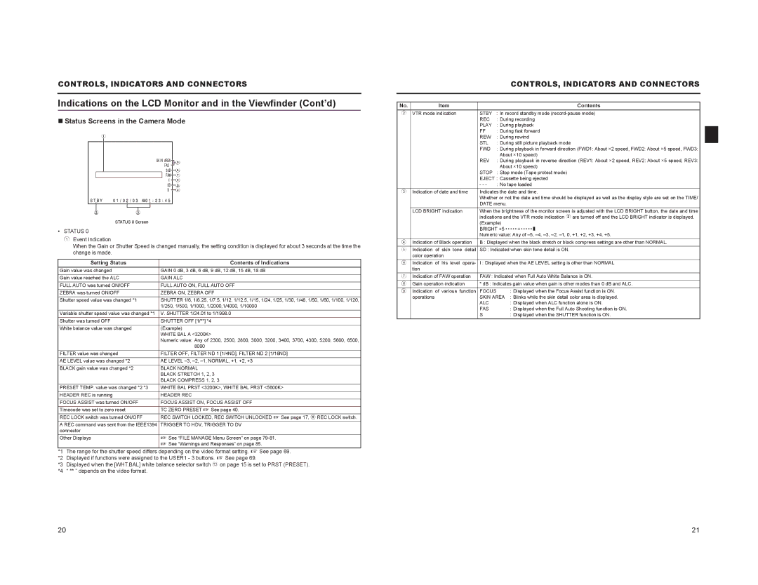
Status Screens in the Camera Mode
| 1 |
| 9 |
| 8 |
| 7 |
| 6 |
| 5 |
| 4 |
2 | 3 |
STATUS 0 Screen
•STATUS 0
1Event Indication
When the Gain or Shutter Speed is changed manually, the setting condition is displayed for about 3 seconds at the time the change is made.
Setting Status | Contents of Indications |
Gain value was changed | GAIN 0 dB, 3 dB, 6 dB, 9 dB, 12 dB, 15 dB, 18 dB |
Gain value reached the ALC | GAIN ALC |
FULL AUTO was turned ON/OFF | FULL AUTO ON, FULL AUTO OFF |
ZEBRA was turned ON/OFF | ZEBRA ON, ZEBRA OFF |
Shutter speed value was changed *1 | SHUTTER 1/6, 1/6.25, 1/7.5, 1/12, 1/12.5, 1/15, 1/24, 1/25, 1/30, 1/48, 1/50, 1/60, 1/100, 1/120, |
| 1/250, 1/500, 1/1000, 1/2000,1/4000, 1/10000 |
Variable shutter speed value was changed *1 | V. SHUTTER 1/24.01 to 1/1998.0 |
Shutter was turned OFF | SHUTTER OFF [1/**] *4 |
White balance value was changed | (Example) |
| WHITE BAL A <3200K> |
| Numeric value: Any of 2300, 2500, 2800, 3000, 3200, 3400, 3700, 4300, 5200, 5600, 6500, |
| 8000 |
FILTER value was changed | FILTER OFF, FILTER ND 1 [1/4ND], FILTER ND 2 [1/16ND] |
AE LEVEL value was changed *2 | AE LEVEL |
BLACK gain value was changed *2 | BLACK NORMAL |
| BLACK STRETCH 1, 2, 3 |
| BLACK COMPRESS 1, 2, 3 |
PRESET TEMP. value was changed *2 *3 | WHITE BAL PRST <3200K>, WHITE BAL PRST <5600K> |
HEADER REC is running | HEADER REC |
FOCUS ASSIST was turned ON/OFF | FOCUS ASSIST ON, FOCUS ASSIST OFF |
Timecode was set to zero reset | TC ZERO PRESET X See page 40. |
REC LOCK switch was turned ON/OFF | REC SWITCH LOCKED, REC SWITCH UNLOCKED X See page 17, 9 REC LOCK switch. |
A REC command was sent from the IEEE1394 | TRIGGER TO HDV, TRIGGER TO DV |
connector |
|
Other Displays | X See “FILE MANAGE Menu Screen” on page |
| X See “Warnings and Responses” on page 85. |
*1 The range for the shutter speed differs depending on the video format setting. X See page 69.
*2 Displayed if functions were assigned to the USER1 - 3 buttons. X See page 69.
*3 Displayed when the [WHT.BAL] white balance selector switch c on page 15 is set to PRST (PRESET). *4 “ ** ” depends on the video format.
|
|
| CONTROLS, INDICATORS AND CONNECTORS |
|
|
|
|
|
|
|
|
No. | Item |
| Contents |
2 | VTR mode indication | STBY | : In record standby mode |
|
| REC | : During recording |
|
| PLAY | : During playback |
|
| FF | : During fast forward |
|
| REW | : During rewind |
|
| STL | : During still picture playback mode |
|
| FWD | : During playback in forward direction (FWD1: About ×2 speed, FWD2: About ×5 speed, FWD3: |
|
|
| About ×10 speed) |
|
| REV | : During playback in reverse direction (REV1: About ×2 speed, REV2: About ×5 speed, REV3: |
|
|
| About ×10 speed) |
|
| STOP | : Stop mode (Tape protect mode) |
|
| EJECT : Cassette being ejected | |
|
| - - - | : No tape loaded |
3 | Indication of date and time | Indicates the date and time. | |
|
| Whether or not the date and time should be displayed as well as the display style are set on the TIME/ | |
|
| DATE menu. | |
| LCD BRIGHT indication | When the brightness of the monitor screen is adjusted with the LCD BRIGHT button, the date and time | |
|
| indications and the VTR mode indication 2 are turned off and the LCD BRIGHT indicator is displayed. | |
|
| (Example) | |
|
| BRIGHT +5 • • • • • + • • • • • O | |
|
| Numeric value: Any of | |
4 | Indication of Black operation | B : Displayed when the black stretch or black compress settings are other than NORMAL. | |
5 | Indication of skin tone detail | SD : Indicated when skin tone detail is ON. | |
| color operation |
|
|
6 | Indication of Iris level opera- | I : Displayed when the AE LEVEL setting is other than NORMAL | |
| tion |
|
|
7 | Indication of FAW operation | FAW : Indicated when Full Auto White Balance is ON. | |
8 | Gain operation indication | * dB : Indicates gain value when gain is other modes than 0 dB and ALC. | |
9 | Indication of various function | FOCUS | : Displayed when the Focus Assist function is ON. |
| operations | SKIN AREA : Blinks while the skin detail color area is displayed. | |
|
| ALC | : Displayed when ALC function alone is ON. |
|
| FAS | : Displayed when the Full Auto Shooting function is ON. |
|
| S | : Displayed when the SHUTTER function is ON. |
20 | 21 |