USING EXTERNAL COMPONENTS
Backup Recording
1.
IEEE1394 switch
IEEE 1394 | VIDEO/Y |
|
| P |
|
OUTPUT | P |
|
LINE |
|
|
DC INPUT | IEEE1394 | Backup unit |
Master unit |
|
|
|
| |
| Signal flow | IEEE1394 cable |
CAUTION
•Set the IEEE1394 switch on both devices to either HDV or DV.
•Start recording after making sure that both devices are properly connected.
OTHERS [2/2] menu screen
Backup Recording of the
IEEE1394 Connector
The
Connections
Use the
Connect the master unit and the backup unit with a IEEE1394 cable.
Settings
Master unit
1.Set the IEEE1394 switch on left side of the
DV | : When backup in DV format |
HDV | : When backup in HDV format |
2.Place in Camera mode.
3.Set the 1394 REC TRIGGER item on the OTHERS [2/2]
menu screen. X See page 78.
Backup unit
• Place in HDV/DV signal input mode.
*Depending on the used component, it may be necessary to set “REMOTE SELECT”.
•When
•Insert the tape and set to STOP or REC PAUSE status.
Operation
Start and stop of recording on the backup unit takes place in accordance with the operation of the REC/VTR trigger button on the master unit.
(Depending on the
MEMO
•When the backup recording is started, the “TRIGGER TO DV” or “TRIGGER TO HDV” indication is shown on the LCD or in the viewfinder for approx. 3 seconds.
•When the Series Recording function of
•If the backup device is equipped with a feature to record time codes input from the IEEE1394 connector (TC DUPLICATE feature), time code data the same as on the master side can be recorded.
•When using
MENU SCREENS
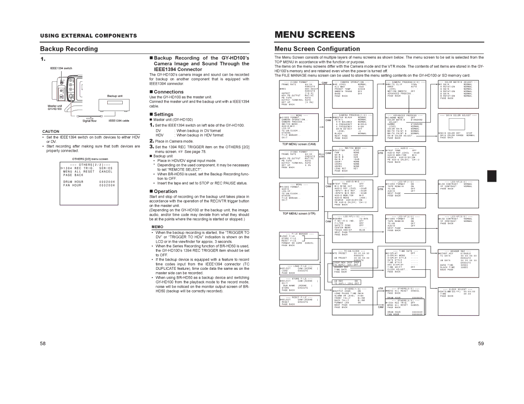
Menu Screen Configuration
The Menu Screen consists of multiple layers of menu screens as shown below. The menu screen to be set is selected from the TOP MENU in accordance with the function or purpose.
The items on the menu screens differ with the Camera mode and the VTR mode. The contents of set items are stored in the GY- HD100’s memory and are retained even when the power is turned off.
The FILE MANAGE menu screen can be used to store the menu setting contents on the
TOP MENU screen (CAM)
TOP MENU screen (VTR)
58 | 59 |