To remove the speaker grilles
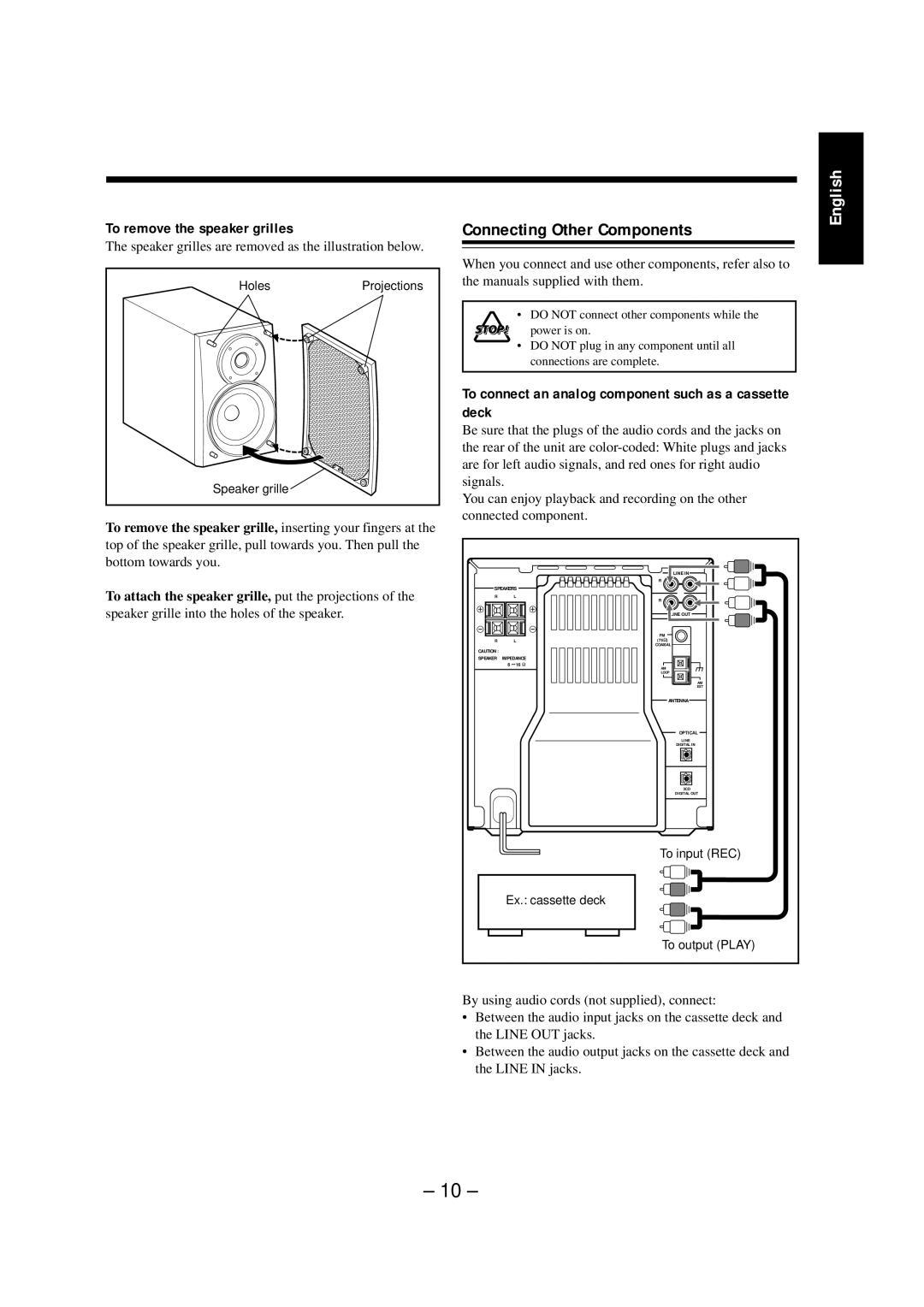
The speaker grilles are removed as the illustration below.
HolesProjections
Speaker grille ![]()
To remove the speaker grille, inserting your fingers at the
top of the speaker grille, pull towards you. Then pull the bottom towards you.
To attach the speaker grille, put the projections of the
speaker grille into the holes of the speaker.
Connecting Other Components
When you connect and use other components, refer also to the manuals supplied with them.
• DO NOT connect other components while the power is on.
•DO NOT plug in any component until all connections are complete.
To connect an analog component such as a cassette deck
Be sure that the plugs of the audio cords and the jacks on the rear of the unit are
You can enjoy playback and recording on the other connected component.
|
|
| LINE IN |
|
|
| R |
SPEAKERS |
| ||
R |
| L | R |
|
|
| |
|
|
| OUT |
|
|
| FM |
R |
| L | (75 ) |
|
|
| COAXIAL |
CAUTION : |
|
|
|
SPEAKER | IMPEDANCE |
| |
| 6 | 16 | AM |
|
|
| LOOP |
|
|
| AM |
|
|
| EXT |
|
|
| ANTENNA |
|
|
| OPTICAL |
|
|
| LINE |
|
|
| DIGITAL IN |
|
|
| 3CD |
|
|
| DIGITAL OUT |
|
|
| To input (REC) |
| Ex.: cassette deck |
| |
|
|
| To output (PLAY) |
By using audio cords (not supplied), connect:
•Between the audio input jacks on the cassette deck and the LINE OUT jacks.
•Between the audio output jacks on the cassette deck and the LINE IN jacks.
English
– 10 –
