Models Equipped With Installation Module
PLANNING
Determine the rouling for the water supply, eleclrical wiring and drain line before proceeding with the actual in- sin!tarpon so that space conflicts do not occur
Important - Do no1 [oute ptumbing or wiring in front of the motor or dishwasher support channels
CUTTING ACCESS HOLES
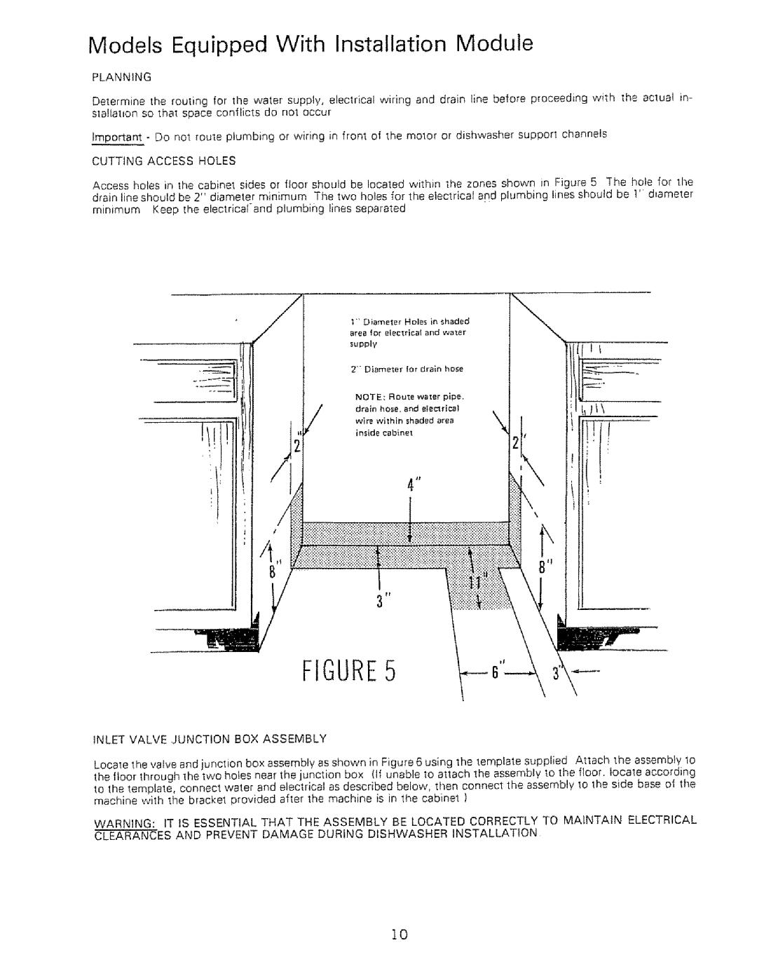
Access holes in the cabinet sides or floor should be located within the zones shown in Figure 5 The hole for lhe drain lineshould be 2" diameter minimum The two holes for the electrical and plumbing lines should be 1" d,ameter
minimum Keep the electricaland plumbing lines separated
fl!:.....
FIGURE5
INLET VALVE ,JUNCTION BOX ASSEMBLY
Locale the valve and junction box assembly as shown in Figure 6 using the template supplied Attach the assembly 1o the floor through 1he two holes near the junction box (If unable to atlach the assembly to the floor, locale according to the template, connect water and electrical as described below, then connect the assembly to the side base ol the machine with the bracket provided after the machine is in the cabinet )
WARNING: IT IS ESSENTIAL THAT THE ASSEMBLY BE LOCATED CORRECTLY TO MAINTAIN ELECTRICAL
CLEARANCES AND PREVENT DAMAGE DURING DISHWASHER INSTALLATION
t0
