| GASKET |
seRE | t!1 k A sEMBL' |
BLOWER PL A*!E
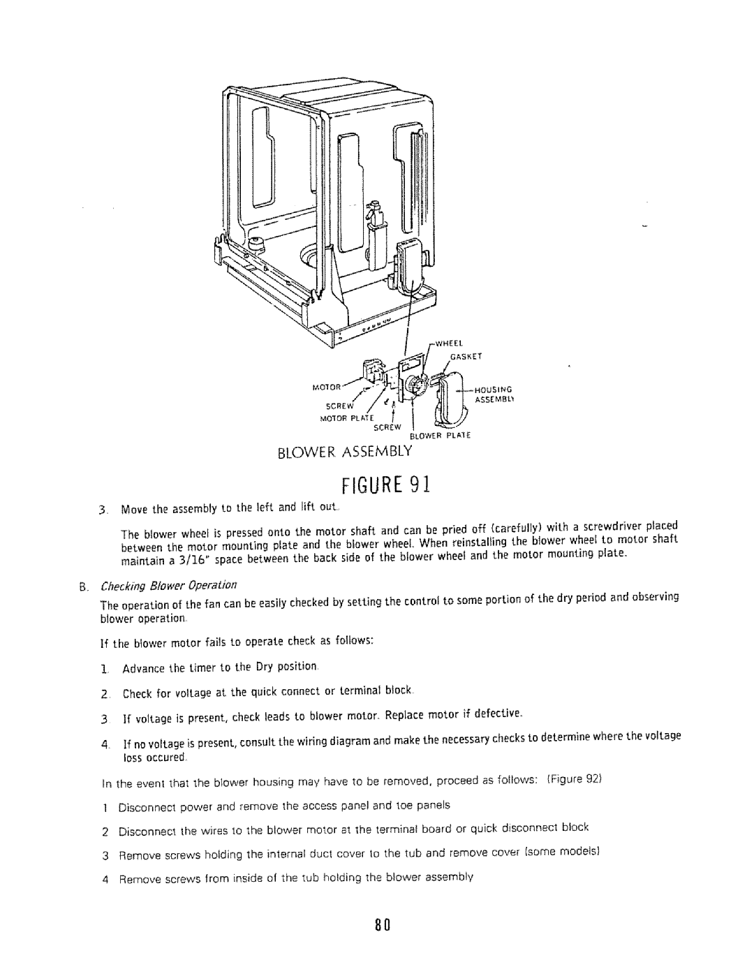
BLOWE R ASSEMBLY
FIGURE9.!
3.Move the assembly to the left and lift out..
The blower wheel is pressed onto the motor shaft and can be pried off (carefully) with a screwdriver placed between the motor mounting plate and the blower wheel When reinstalling the blower wheel to motor shaft maintain a 3/&6" space between the back side of the blower wheel and the motor mounting plate°
B,, Checking Blower Operadon
The operation of the fan can be easily checked by setting the control to some portion of the dry period and observing blower operation,
if the blower motor fails to operate check as follows:
!, Advance the timer to the Dry position,
2, Checkforvoltageat thequickconnector terminalblock
3If vo]tage is present, check leads to blower motor. Replace motor if defective.
4If no voltage is present, consult the wiring diagram and makethe necessarychecksto determine where the voltage lossoccured
In the event that the blower housing may have to be removed, proceed as follows: (Figure 92)
1 Disconnecl power and remove the access panel and toe panels
2Disconnect the w}res to the blower motor at the terminat board or quick disconnect block
3Remove screws holding the internal ducl cover to the tub and remove cover (some models}
4Remove screws from inside of the tub holding the blower assembly
8O
