Automatic Dishwashers
We Service Wh,t We Sell
If ever you need us -- were available You Can Count On Us
Sears t
Contents
Introduction
WATER, Detergent and the Automatic Dishwasher
Removal and Control of Hard Water Film
Extremely hot water
Bronze Tarnish on Silverware
Possible Cause & Solution
Filming
Black Marks on Dinnerware
Cleaningmineraldepositsfromporcelainsurfaces
Attach Screws Access Panel
Installation
2HOLE or Larger
Drain Hose Connected to Disposer
Or y Branch
Sink X,,T Left
Drain Hoseconnectionto Sink Drain
Drain Hose Connection Through Floor
Cutting Access Holes
Inlet Valve ,JUNCTION BOX Assembly
Electrical
Circuit Conductorground Wire
Green Ground Screw
GROUND1NGINSTRUCTIONS
HOT Wate Line
Reen Ground Screw
Shut OFF VA LV E
Trap P or Above
Drain
HOW to POSITION, ALIGN, and LEVEL, Your Dishwasher
Sink AI Left Sink AT Right
TWO Ways to Anchor Your Dishwasher
Two Level Wash Feature
Wjash System
Switch
Testing Water Charge Level
Spray Arm Assembly
Ttttt
Three Level Wash System
Pushlodgedparticles
Removal of Upper Spray Arm Only
Bearing Assembly
Removal of Mtddle Spray Arm
Side
Water Inlet Valve
Plunger Hole Line Water Pressure
Washer Atmospheric PRESSURE£ B
Plunger Diaphragm
Flow Washer
Testing
Sen/zcing
45 sec
Metal Washer Flow Plastic Retainer
Curved Side Screen Sealer Washer
Marking
Page
Towaterinletvalve
WA1ERiNLETASSEMBLY
Side Water Inlet, Steam Trap and Venting
Plasticnut
Exit Flow of Moist AIR During DRY Cycle Vent
Motor and Pump Assembly Assembled
Inner Door
Pump Assembly
PU M P Plate
Bottom of Relay
Main Motor and Relay
Page
Housin With the recirculating
System Uses Same Pump Housing aS u L
Level Tower Pump 5y,srem This
Osed Off For this Reason He bwer Utltz,es a. lower
Motor Main or Run Winding Check
Timer
Testing the Motor and Relay
Position
Relaystart
Check the voltage as shown in Position C
TAR. T .,..BLUE-ORANGE Timer t- Relay
Motor Start Circuit Wash and Rinse Cycle
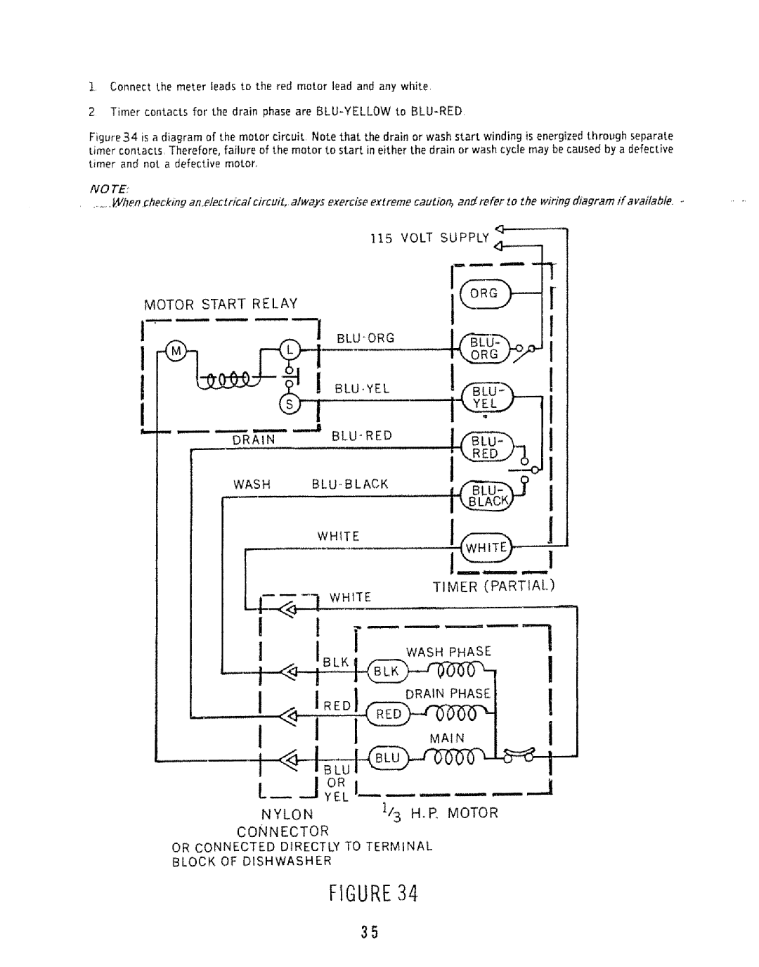
Motor 5tart Circuit Drain Cycle
Wash
115
Volt Supply Motor Start Relay
Or Connected Directly to Terminal Block of Dishwasher
Terminal
WAs.ER
CA U T/OiM
Center Motor Shaft with Pump Housing With Service Tool
ROD
Motor nstaltation
Install Ihese Screws First TUB
Hoses and Couplers
No TE
Hose and Coupler Assembly 8 compact model
Sleevegasket
Faucet Coupler
Ring
Dispensers
Detergent DLpenser- B/-Metal Operated
Description
Into Fill Neck
Wetting Agent Dispenser Bi-Metal Operated
Fill Neck Scoop Wetting Agent Liquid
Drainsback .J Ntosupp
FIGUP,E
CAM
Timers
CAM Switch
Motor
Selector Switches
Checking The 5-Button Swttch
Mylar Jacket
Thermostats and Temperature Indicators
Sam-Wash or High Temperature Wash/Rin.se Thermostat
Checking Thermostat Operation
Figurego
Iii ii!ii!!i!i
Iiiiiiiii
DRY
SanM4/ash Delay Circuit
4tfi Rinse
Water Heat Option Hot Rinse
Sanitize Delay Light Circuit Power Sani Wash Cycle Selector
Page
FIGUREG3C
Page
TCH on
Door and Float Switches
Door Latches and Switches
FLO Switch
Cycle Charts
Ester Line Charts
Example
Fill Phase Normal Cycle
Page
Relay Switch Opens After Motor Starts
First Wash Normal Cycle
Voltage Checks
Continuity Check
Door Assemblies
One Piece Outer Door Control Panel
Two Piece Outer Door Control Panel
£RING
Anti Tilt Assembly38 Portable Models
Arm Replacement 8 Dishwashers
Racks
END CAP Rack
Tub Gaskets
Upper Front Lower Rear Roller
To Replace
Page
Cord Reel
Caster Replacement Potlable Dishwashers
Casters
Tubs
Drying System
Convection Method
Forced Air Method
SeRE A sEMBL
Checking Blower Operadon
Operation
Heating Elements
Heating Element
Hot Dry Cool Dry Power Miser SWHch
Eatersymbol
Heater Testing
Power Miser Circuits Single Pole Double Throw Switch
Power Miser
Orange BUS Timer
Heater White
Blower
Trouble Shooting
General Trouble Shooting
Check selector switch per wiring diagram
Turn knob until pitot light burns never turn into fill
Instructions
Motor Shaft Seal are
Lever
Water Leaks
Door liner
807042
806863
806565
806898
DIV 22 Source 587 Part Noo

